2OM-1733-005w_F8.pdf - 第178页
2OM-1733 2-3-44 3.7 Placement (G01) Placement [1] [2] [3] [4] Fig. 2B3-36 [1] T ool Bar The operation commands that can be executed in the "Placement" window, are collectively displayed as icons. Table 2B3-3 Ic…

2OM-1733
2-3-43
(F01_07)
Fdr No.
When "Enable" is selected for the feeder alternate function, set the
destination feeder No. (Fdr No.) of the feeder that will work in place of the
feeder where a component pickup error has occurred in succession.
(F01_08)
Component Library Comment
Shown are the comments that were entered in the component library data.
(F01_09)
Carrier Type, Dir [deg], and Width [mm]
Shown are the values specied in the component library data.
(F01_10)
Fd. Pitch [mm]
Shown are the feed pitches specied in the component library data.
(F01_11)
Used Parts
Shown is the number of components to be used for one unit PCB.
(F01_12)
Nozzle Type
Shown is the number of components to be used for one unit PCB.
1204-001
3.6 CMPNT PL
2OM-1733
2-3-44
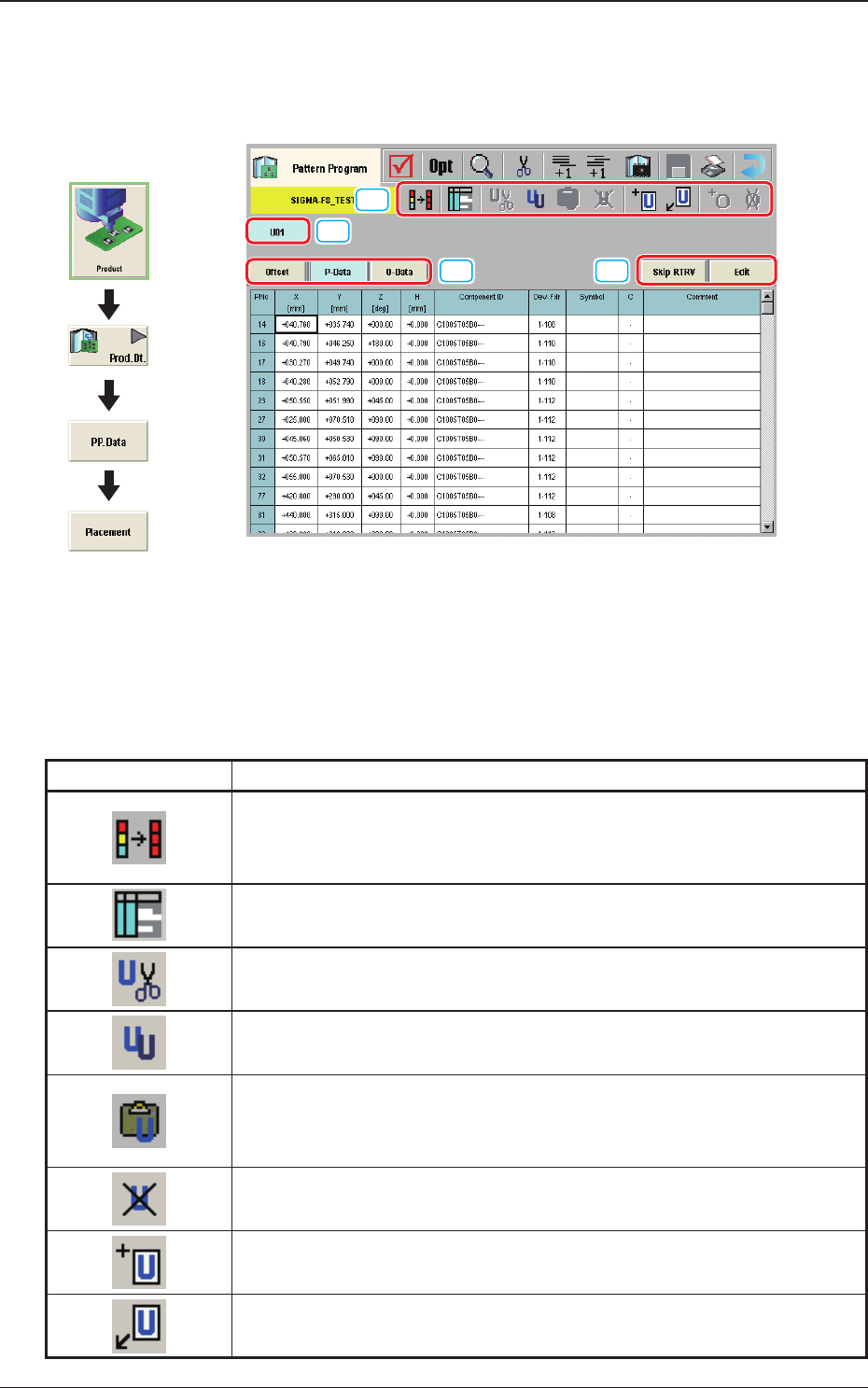
3.7 Placement
(G01) Placement
[1]
[2]
[3]
[4]
Fig. 2B3-36
[1] Tool Bar
The operation commands that can be executed in the "Placement" window,
are collectively displayed as icons.
Table 2B3-3
Icons Description
When pressed, the head of the selected two or more placement data items
is copied onto the other data. The head data of the selected two or more
P/O data items is copied onto the other selected data.
When pressed, the "Symbol Data" window appears.
When pressed, the selected unit is copied and deleted.
The currently displayed U-data is cut out.
When pressed, the selected unit is copied.
The currently displayed U-data is copied.
When pressed, the copied unit is inserted.
The U-data (the selected unit is copied and deleted, or the selected unit is
copied) is pasted.
When pressed, the selected unit is deleted.
The currently displayed U-data is deleted.
When pressed, new unit is added at the end.
New U-data is added to the end of the U-data.
New unit is inserted before the selected unit.
New U-data is inserted before the currently selected U-data.
Graphic
Development
1212-002
3.7 Placement
2OM-1733
2-3-45
Table 2B3-4
Icons Description
The O-data is added to the selected unit.
The O-data is added to the currently selected U-data.
The O-data in the selected unit is deleted.
The O-data in the currently selected U-data is deleted.
[2] [Skip RTRV] Button
When pressed, the search of the unit where the unit control has been set to
"Skip", is started up.
When the [Skip RTRV] button is pressed, the offset window for the unit
where the unit control has been set to "Skip", is displayed.
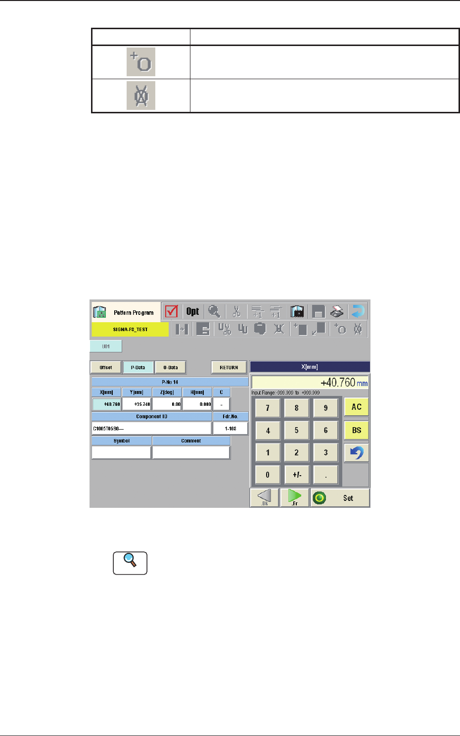
[Edit] Button
When this button is pressed, the P-Data or O-Data is edited.
When the data to be edited is selected and the [Edit] button is pressed, the
"Data Setting" window appears.
Fig. 2B3-37
Reference
Refer to (G03) or (G04) for each item to be set.
[3] Placement Data Group Select Button
Using this button, the placement data group is selected.
[4] Placement Data Select Button
Using this button, the placement data is selected.
1212-002
3.7 Placement