2OM-1733-005w_F8.pdf - 第184页
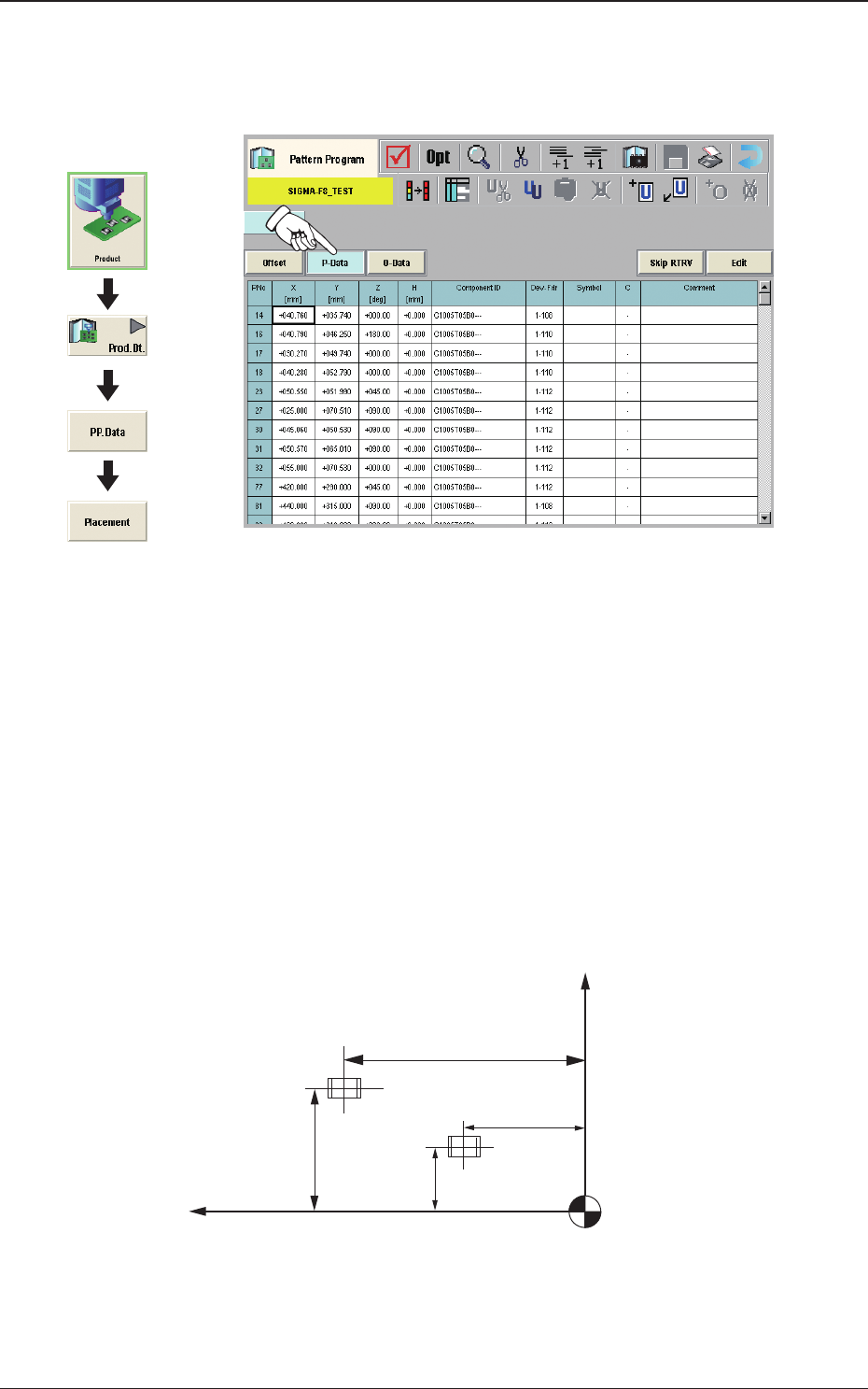
2OM-1733 2-3-50 (G03) P-Data When the [P-Data] button is pressed in the "Placement" window, the following tab sheet appears. Fig. 2B3-42 (G03_01) PNo Shown are the step Nos. of the placement data (P). Set coord…
2OM-1733
2-3-49
(G02_04)
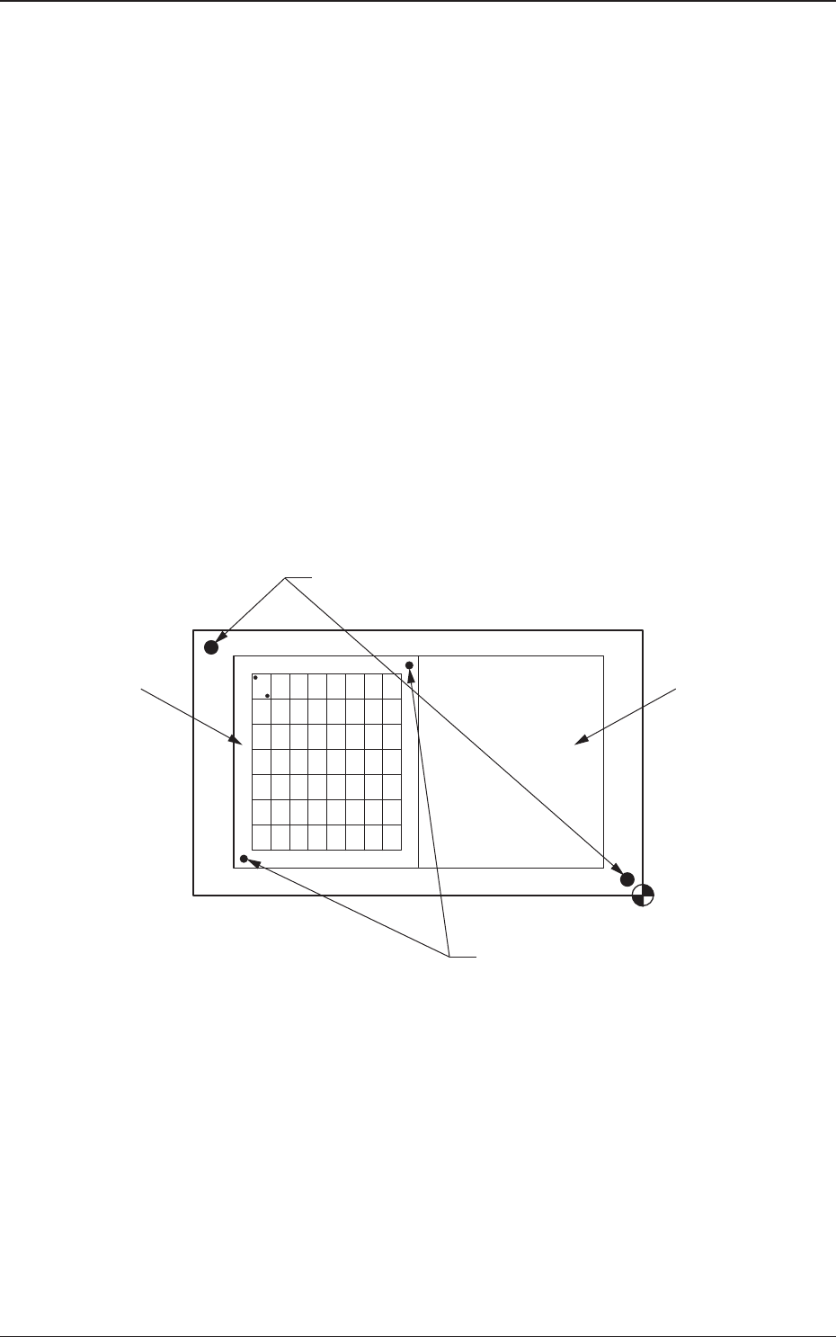
Recog Coord X1 [mm] and Recog Coord Y1 [mm]
Set the X1 and Y1 coordinates of the rst ducial mark based on the pattern
origin.
Recog Coord X2 [mm] and Recog Coord Y2 [mm]
Set the X2 and Y2 coordinates of the second ducial mark based on the
pattern origin.
(G02_05)
Fiducial Mark FM1 and Fiducial Mark FM2
Set the mark Nos. of the rst and second ducial marks FM1 and FM2.
Select the mark Nos. (Mark Codes) specied in the PEC recognition mark
data of the operation data.
(G02_06)
Unit PCB Recognition
One to three points are setup for the PEC recognition for each U data.
U02U01
Global Recognition
Unit PCB Recognition
Fig. 2B3-41
1212-002
3.7 Placement
2OM-1733
2-3-50
(G03) P-Data
When the [P-Data] button is pressed in the "Placement" window, the
following tab sheet appears.
Fig. 2B3-42
(G03_01)
PNo
Shown are the step Nos. of the placement data (P).
Set coordinates and angles for component placement in the lines of the step
Nos. (P-Nos.).
(G03_02)
X [mm] and Y [mm]
Set Coordinates X and Y for component placement. The coordinates must be
based on the placement coordinate reference (N0).
Y2
Y1
X1
X2
Y
X
Placement Coordinate Reference (No)
Fig. 2B3-43
Graphic
Development
1212-002
3.7 Placement
2OM-1733
2-3-51
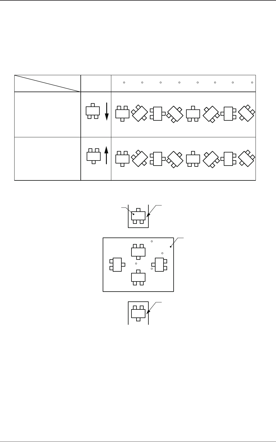
(G03_03)
Z=theta [deg]
Set angles for component placement.
The placement angles must be determined according to the packaged posture
of components on the tape feeder.
Example:
0 45 90 135 180 225 270 315
Front Side of Machine
Z=Theta
(Angle)
Feeder Bases #1
Packaged
Posture
User Direction
of Tape Feed
Packaged
Posture
User Direction
of Tape Feed
Feeder Bases #2
Rear Side of Machine
Packaged Posture of
Component on Feeder
Tape Feeder
PCB
Tape Feeder
0
90
180
270
Fig. 2B3-44
1212-002
3.7 Placement