2OM-1733-005w_F8.pdf - 第161页
2OM-1733 2-3-27 (D01_02) PCB Finishing Position The PCB Finishing Position is selected in this text box. Output The component placement is performed on the downstream side. Note The PCB nishing position should be xed o…
2OM-1733
2-3-26
3.4 Control
(D01)
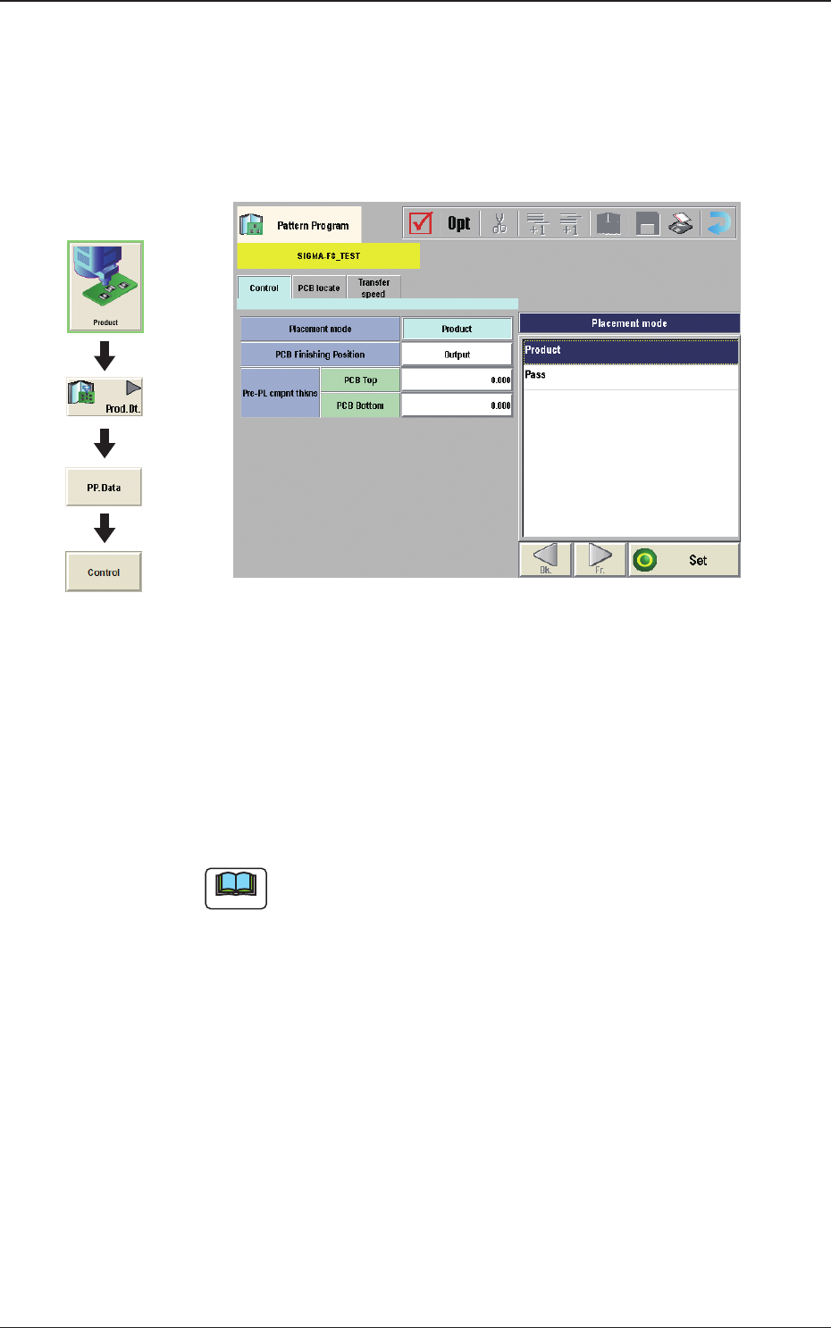
Control
When the [Control] tab is pressed in the "Control" window, the following tab
sheet appears.
Fig. 2B3-25
(D01_01)
Placement mode
"Product" or "Pass" is selected for the placement mode in this pane.
Normally, "Product" is selected.
Product
: When selected, the placement operation is performed.
Pass
: When selected, the PCB is passed without placement.
Note
When the pattern program set to "Pass", is setup on the Pattern Program
Data, the vacuum pump is automatically turned OFF.
Graphic
Development
1212-002
3.4 Control
2OM-1733
2-3-27
(D01_02)
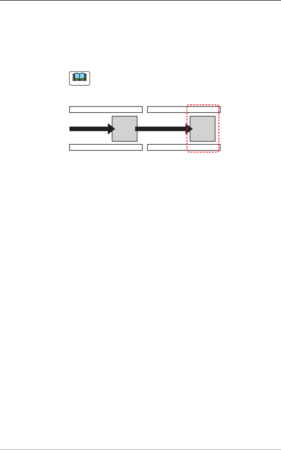
PCB Finishing Position
The PCB Finishing Position is selected in this text box.
Output
The component placement is performed on the downstream side.
Note
The PCB nishing position should be xed on the downstream side.
Production Position
Fig. 2B3-26
1212-002
3.4 Control
2OM-1733
2-3-28
(D01_03)
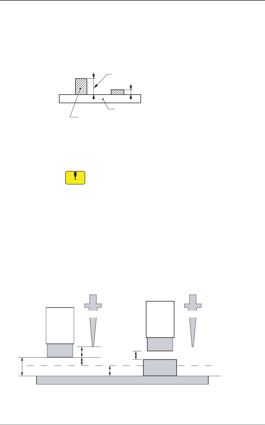
Pre-PL cmpnt thkns
PCB Top [mm]
When some components are placed previously on a PCB by the input
machine, etc., and transferred to the main machine, be sure to enter the
thickness of the tallest component of all in the text box.
Tallest Previously Placed Component
Set this thickness in the text box.
PCB
Fig. 2B3-27
•
Data Input Range
0 to 2.000 (0 to 12.700)
Notice
(a) When components are placed previously and the main machine
is operated with "0.00" (no previously placed components) in
this text box, some of the previously placed components may
interfere with components to be placed newly.
(b) It is advisable that placement data should be created such that
shorter components are placed before the tallest one.
(c) Whenthespeciedthicknessofapreviouslyplacedcomponent
differs from the actual one, the light emitter of the linear
measure sensor may interfere with the previously placed
component.
(d) Theguresforthesettingrangeinbracketsshowthevalues
for the high-speed head SIGMA-F8 (HL).
2.0 mm
4.0 mm
2.0 mm
3.0 mm
2.0 mm
NL Origin Position NL Origin Position
Light
Emitter
Light
Emitter
Previously
Placed
Component
PCB
Placement Level
No Previously Placed Component Previously Placed Component
Fig. 2B3-28
1403-004
3.4 Control