2OM-1733-005w_F8.pdf - 第173页
2OM-1733 2-3-39 1212-002 3.5 PL Head/Nozzle 3.5 PL Head/Nozzle (E01) Nozzle Place When the [Nozzle Place ] tab is pressed in the "PL Head/Nozzle" window, the following tab sheet appears. Fig. 2B3-33 (E01_01) No…
2OM-1733
2-3-38
(D03_04)
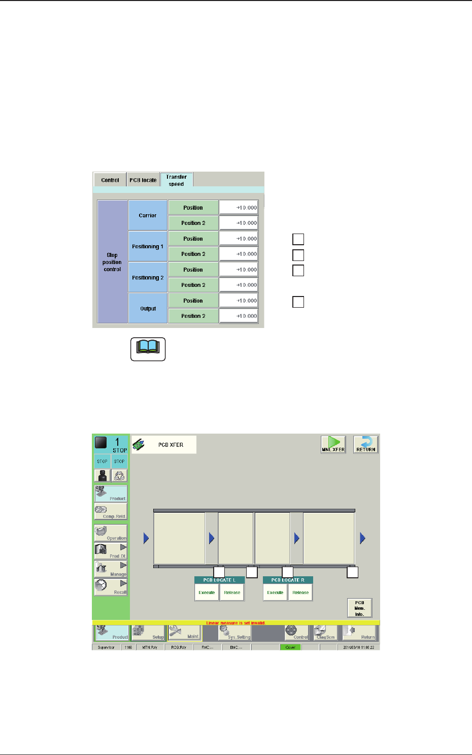
Stop position control
Carrier, Positioning 1, Positioning 2, Output
The following items are set for "Reload", "Positioning 1", "Center",
"Positioning 2"and "Discharge".
Position [mm]
The distance from the position of the PCB detected using the stop sensor
to the PCB stop position, is set in this text box.
……… 1
……… 2
……… 3
……… 4
4 3
1
2
Fig. 2B3-32-1
1403-004
3.4 Control
Note
The relationship between the settings and the PCB stop positions is as
follows.
When any of the stop positions "1" through "4" shown in the upper
window in the gure, is changed, the distance from the PCB detection
in the positions "1" through "4" in the lower window in the following
gure, to the PCB stop position, is changed accordingly.
2OM-1733
2-3-391212-002
3.5 PL Head/Nozzle
3.5 PL Head/Nozzle
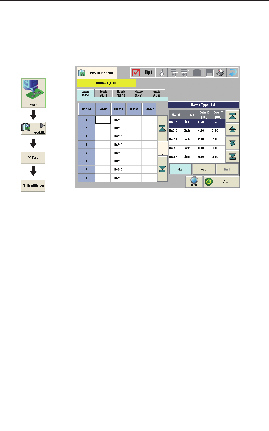
(E01) Nozzle Place
When the [Nozzle Place] tab is pressed in the "PL Head/Nozzle" window,
the following tab sheet appears.
Fig. 2B3-33
(E01_01) Nozzle Place
Head 11, 12, 21, 22
Nozzle No. 1 to 15
This data is used to allocate the nozzles to the specied positions (Nozzle
Allocation Nos.) on the heads.
Graphic
Development
2OM-1733
2-3-40
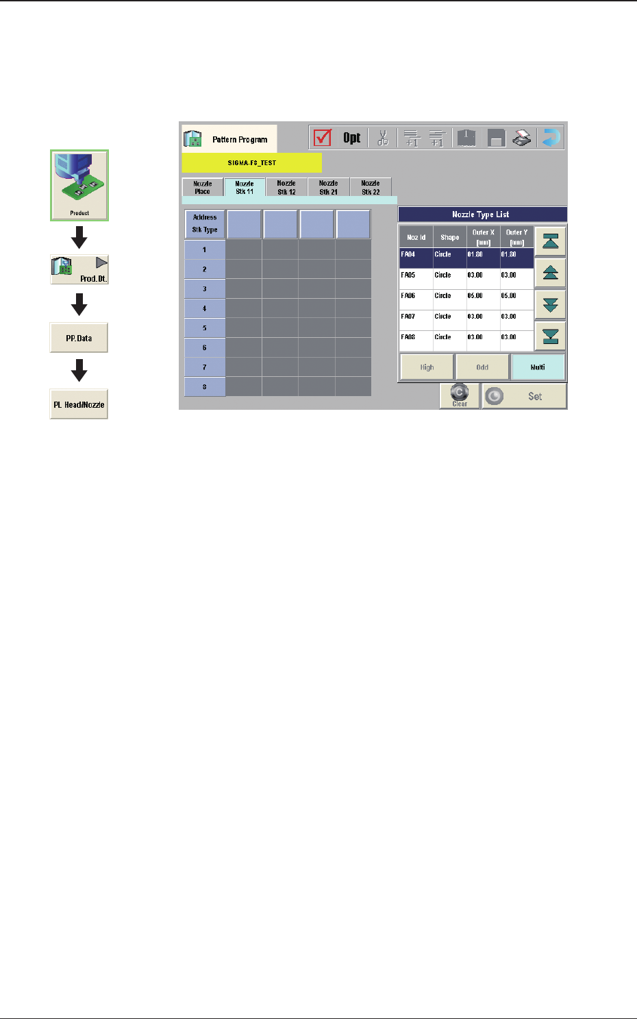
(E02) Nozzle Stk 11, 12, 21, 22
When the [Nozzle Stk 11], [Nozzle Stk 12], [Nozzle Stk 21] or [Nozzle Stk
22] tab is pressed on the "PL Head/Nozzle" window, the following tab sheet
appears.
Fig. 2B3-34
(E02_01) Nozzle Stk 11, 12, 21, 22
Address Stk Types 1 to 15
Using these parameters, the nozzles are housed in the specied positions
(address stocker type) in the nozzle stocker.
High
: 1 to 15
Graphic
Development
1212-002
3.5 PL Head/Nozzle