2OM-1733-005w_F8.pdf - 第142页
2OM-1733 2-3-8 (B01_04) Placement Reference Set the PCB positioning reference in this text box. The reference must be specied according to the input and output machines. Rear Left : The placement coordinate reference is…
2OM-1733
2-3-71212-003
3.2 PCB
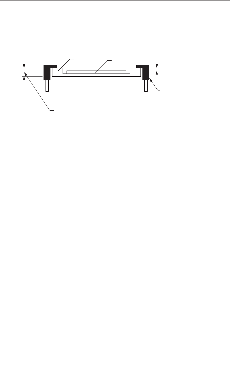
Example of Jig PCB Usage
The gure below shows that the upper surface of a PCB is lower than the
PCB upper surface reference.
If "PCB Upper Surface Reference + a" is set as an offset value at this time,
components can be placed correctly on the PCB.
a
T (Thickness)
Jig PCB
PCB
PCB Upper Surface
Reference
Chute
Fig. 2B3-8
2OM-1733
2-3-8
(B01_04)
Placement Reference
Set the PCB positioning reference in this text box. The reference must be
specied according to the input and output machines.
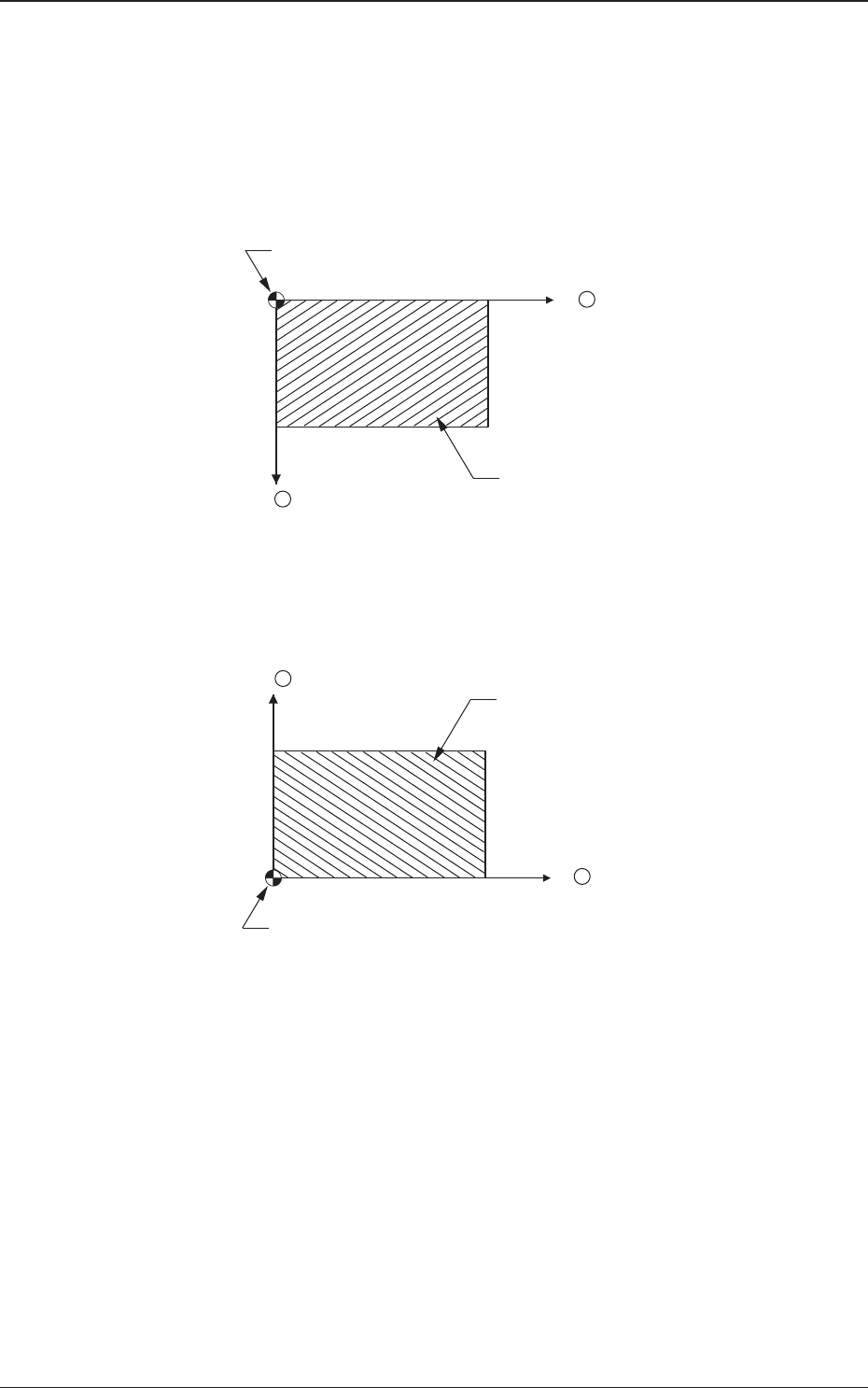
Rear Left
: The placement coordinate reference is based on the rear left
side and specied as follows.
X +
Y +
Placement Coordinate Reference (No)
PCB
Fig 2B3-9
Front Left
: The placement coordinate reference is based on the front left
side and specied as follows.
X +
Y +
Placement Coordinate Reference (No)
PCB
Fig. 2B3-10
1212-002
3.2 PCB
2OM-1733
2-3-9
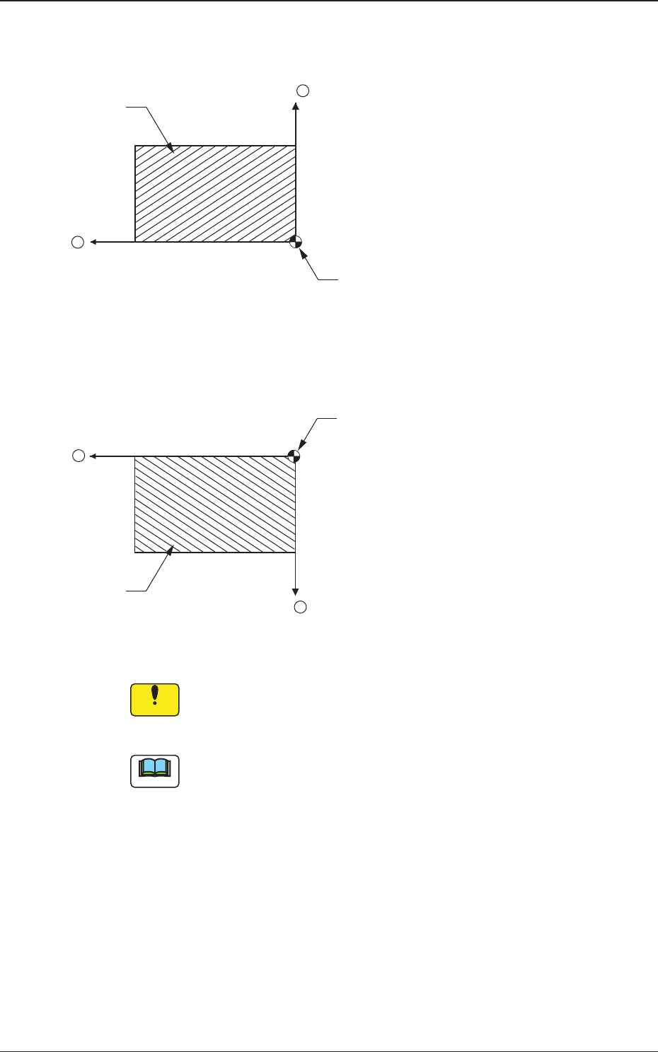
Front Right
: The placement coordinate reference is based on the front
right side and specied as follows.
X +
Y +
Placement Coordinate Reference (No)
PCB
F2B3-11
Rear Right
: The placement coordinate reference is based on the rear
right side and specied as follows.
X +
Y +
Placement Coordinate Reference (No)
PCB
F2B3-12
Notice
Be sure to set the same reference as the input and output machines.
Ifareferencedifferentfromtheinputandoutputmachinesisspecied,
PCBs cannot be produced correctly.
Note
When a different reference is specied in the pattern program and the program
is to be used for this machine, be sure to change the reference of this machine to
the different one.
1212-002
3.2 PCB