2OM-1733-005w_F8.pdf - 第293页
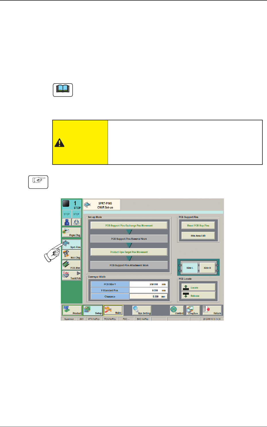
2OM-1733 6-4-3 [5] "PCB Locate" Group Box [Locate] Button : When pressed, this button moves up the Z clamp and the backup base and locates the PCB. [Release] Button : When pressed, this button moves down the Z …
2OM-1733
6-4-2
Fig. 2F4-3
When "Disable (Manual Change)" has been set up for "Support Pin Setting",
the above is displayed.
[2] "Noz Chg." Group Box
[Reset] Button
When this button is pressed and within 10 seconds, the [START] button on
the operation panel is pressed, the support pins are housed in the nozzle area.
[3] "PCB Support Pins" Group Box
[Reset PCB Sup.Pins] Button
When the [START] button is pressed in 10 seconds after this button, the
support pins are housed in the stock area.
[Stkr.Area Edit] Button
In the case that the PCB support pins are to be moved manually or an error
occurs, the stock area parameters are edited.
When the [Stkr.Area Edit] button is pressed, the "Stkr.Area Edit" window
appears.
Reference
Refer to "4.4.1 Stkr.Area Edit Procedure" for the details of the
"Stkr.Area Edit" window.
[4] PCB Locate Section Select Buttons
When pressed, the PCB positioning section on the side where the setup
operation is to be performed, is selected.
[Side L] Button :
PCB Locate L Section
[Side R] Button :
PCB Locate R Section
1212-002
4. "CNVR Set-up" Window

2OM-1733
6-4-3
[5] "PCB Locate" Group Box
[Locate] Button
: When pressed, this button moves up the Z clamp and
the backup base and locates the PCB.
[Release] Button
: When pressed, this button moves down the Z clamp and
the backup base and releases the PCB locating.
[6] "Conveyor Width" Group Box
PCB Size Y, Y Standard Pos.
The "PCB size Y" and "Y Standard Pos." set on the pattern program data for
the product model, are shown in these data boxes.
[Clearance] Button
When this button is pressed, the "Clearance" window opens. Enter the value
as a leeway between the conveyor width and the PCB. The entered value
appears in the text box beside this button.
The actual conveyor width becomes "PCB Size Y + Clearance (Recommended
Value: 0.5 mm)".
1212-002
4. "CNVR Set-up" Window
2OM-1733
6-4-4
4.1 Collection of PCB Support Pins and Setup Operation of
Conveyor Width
•
For Support Pin Manual Change)
The PCB support pins are used to keep the upper surface of the PCB in proper
height for stabilization of the component placement. If the conveyor width is
not correctly set, the PCB support pins cannot be attached correctly.
Note
When 0402 and 0603 components must be placed, it is important to secure the
atness of the PCB. Use the support pins or a backup plate.
Consult the marketing department or sales agency of Yamaha Motor Co., Ltd.
for how to make a backup plate.
CAUTION
The load power to the motors, etc., is turned OFF
but the setup operation must be performed carefully
when you put your hand inside the machine. Avoid
handandngerinjuries.
Procedure
(1) Press the [CNVR Set-up] button on the submenu bar to display the "CNVR
Set-up SPRT-PINS" window.
Fig. 2F4-4
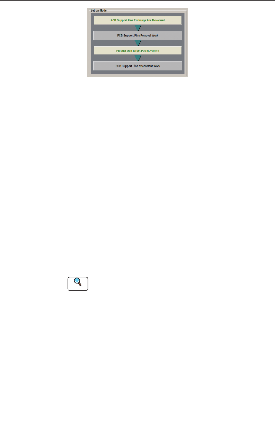
(2) Press the [PCB Support Pins Exchange Pos. Movement] button.
After that, press the [START] button on the operation panel in 10 sec.
(The machine retracts the head and maximizes the conveyor width.)
(3) Press the cover lock switch.
(The transparent cover will be unlocked).
1212-002
4.1 Collection of PCB Support Pins and Setup Operation of Conveyor Width