2OM-1733-005w_F8.pdf - 第323页
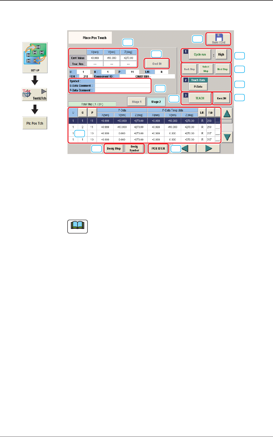
2OM-1733 6-7-5 7.2 "Place Pos T each" Window [1] [2] [3] [5] [4] [12] [6] [7] [8] [9] [10] [11] Fig. 2F7-6 [1] "Step No."Display Section The step data selected in the "Desig Step"(Designate …
2OM-1733
6-7-4
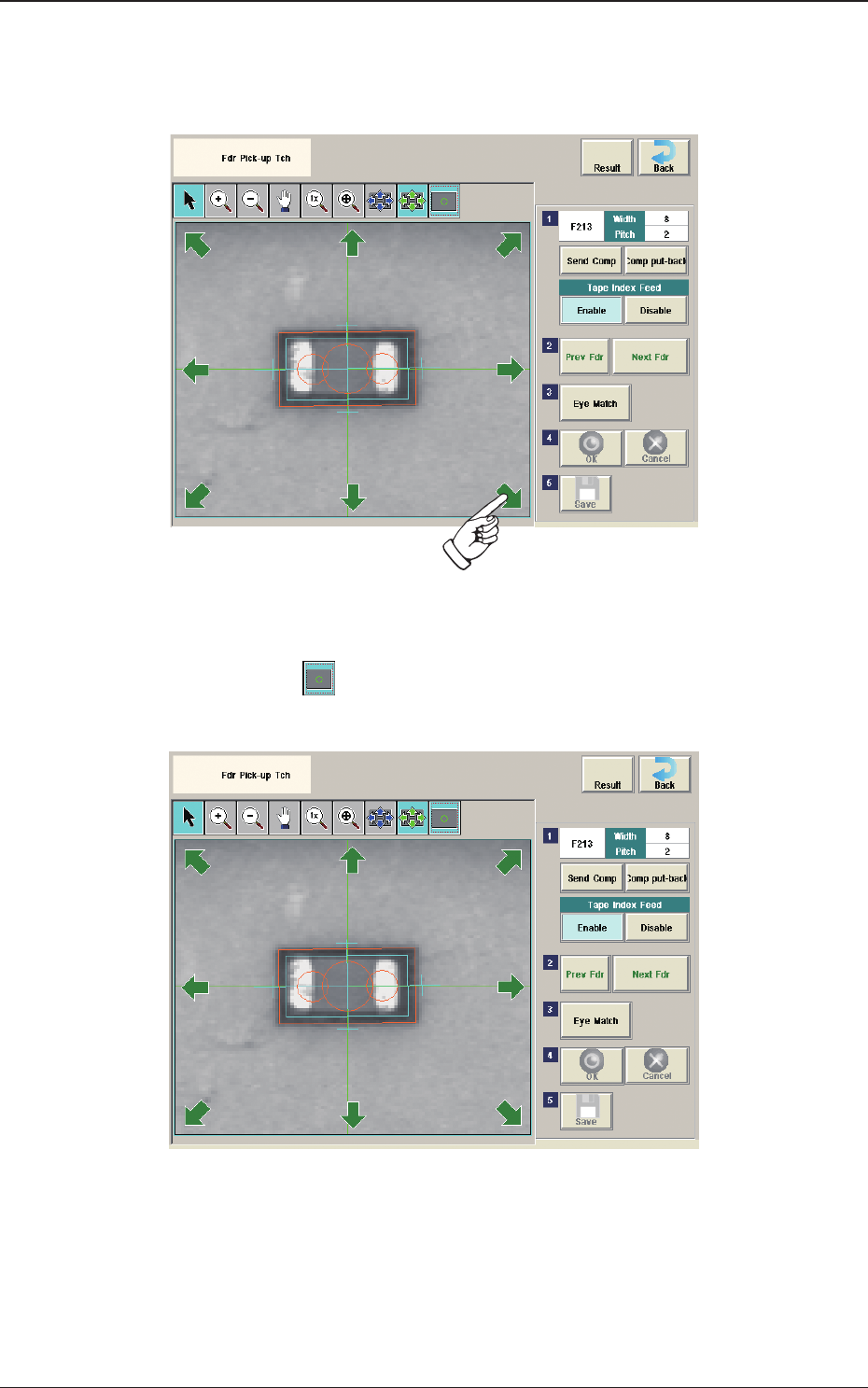
(6) Press the [Eye Match] button.
(Start the manual alignment operation from the position shown using an
arrow).
Fig. 2F7-4
(7) Press the [
] button if necessary.
(Check the nozzle pick-up position).
Fig. 2F7-5
(8) When the manual alignment operation is completed, press the [OK] button.
(In the case that the performed manual alignment is cancelled, press the
[Cancel] button.)
(9) Press the [Save] button to save the manual alignment results.
1212-001
7.1 "Fdr Pick-up Tch" Window
2OM-1733
6-7-5
7.2 "Place Pos Teach" Window
[1]
[2] [3]
[5]
[4]
[12]
[6]
[7]
[8]
[9]
[10]
[11]
Fig. 2F7-6
[1] "Step No."Display Section
The step data selected in the "Desig Step"(Designate Step) operation, is
displayed.
Note
Normally, the Item are displayed in the order of component placement.
However, pressing the [Desig Symbol] button can arrange them in
ascending order.
Graphic
Development
1212-002
7.2 "Place Pos Teach" Window
2OM-1733
6-7-6
[2] [Desig Step] snd [Desig Symbol] Button
[Desig Step] Button
Using this button, the starting step No. is selected in the case that the
placement position teaching is started from any step No. in the pattern
program.
The background color for the selected Step No., turns pale blue.
The serial setup of the "Starting Step No.", "U", "O", and "P" Nos. is
available in the input window displayed when the [Desig Step] button is
pressed.
Note
Normally, the Item are displayed in the order of component placement.
However, pressing the [O] or [P] button can arrange them in ascending
order.
[Desig Symbol] Button
Using this button, the starting symbol name is selected in the case that the
placement position teaching is started from any symbol name in the pattern
program.
The background color for the selected symbol turns pale blue.
The starting symbol name can be selected in the input window displayed
when the [Desig Symbol] button is pressed.
Note
Normally, the Item are displayed in the order of component placement.
However, pressing the [Desig Symbol] button can arrange them in
ascending order.
[3] [PCB XFER] Button
When this button is pressed the "PCB XFER" window appears.
Reference
Refer to "6. "PCB XFER" window" in Chapter 6 for the details.
[4] Placement Data
The pattern program position presently referred and the position resultant
from the teaching are indicated.
[5] [Cycle run] Button
When the [START] button on the operation panel is pressed in 10 seconds
after this button, the "Recognition" window appears and the X/Y beam starts
moving automatically in succession according to the pattern program.
When the [STOP] button on the operation panel is pressed during the
movement, the X/Y beam stops after the 1-step operation.
Note
Select [High], [Mid] or [Low] for the movement speed in this selection
box.
1212-002
7.2 "Place Pos Teach" Window