2OM-1733-005w_F8.pdf - 第343页
2OM-1733 6-7-25 7.4 "Plc Pos Corr T ch" Window This window enables the operator to measure the placement position correction data and reect the measurement results on the pattern program. [1] [2] [3] [6] [5] […

2OM-1733
6-7-24
•
PEC Recognition Test Execution
Procedure
(1) Press the [START] button on the operation panel within 10 seconds after
pressing the [Recog] button.
(The PEC recognition operation are performed.)
When the "Mrk Pos Align" has been set to "Enable" and the recognition test
is completed successfully, the XY beam is moved so that the PEC recognition
mark is located at the center on the recognition monitor.
•
When the recognition test fails, an error (recognition error) window
appears.
Collect each parameter referring to the descriptions in the "Error" window
and perform the PEC recognition test again.
•
When the recognition test is completed successfully, make a note of
collected parameters and reflect them onto the pattern program data for the
product PCB to be tested.
1212-001
7.3 "PEC RCG" Test Window
2OM-1733
6-7-25
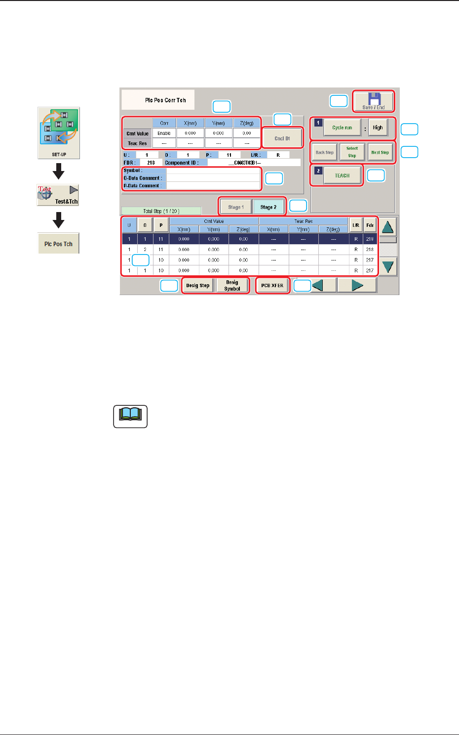
7.4 "Plc Pos Corr Tch" Window
This window enables the operator to measure the placement position correction
data and reect the measurement results on the pattern program.
[1]
[2] [3]
[6]
[5]
[11]
[7]
[8]
[4]
[9]
[10]
Fig. 2F7-20
[1] "Step No."Display Section
The step data selected in the "Desig Step"(Designate Step) operation, is
displayed.
Note
Normally, the Item are displayed in the order of component placement.
However, pressing the [Desig Symbol] button can arrange them in
ascending order.
Graphic
Development
1212-001
7.4 "Plc Pos Corr Tch" Window
2OM-1733
6-7-26
[2] [Desig Step] snd [Desig Symbol] Button
[Desig Step] Button
Using this button, the starting step No. is selected in the case that the
placement position teaching is started from any step No. in the pattern
program.
The background color for the selected Step No., turns pale blue.
The serial setup of the "Starting Step No.", "U", "O", and "P" Nos. is
available in the input window displayed when the [Desig Step] button is
pressed.
Note
Normally, the Item are displayed in the order of component placement.
However, pressing the [O] or [P] button can arrange them in ascending
order.
[Desig Symbol] Button
Using this button, the starting symbol name is selected in the case that the
placement position teaching is started from any symbol name in the pattern
program.
The background color for the selected symbol turns pale blue.
The starting symbol name can be selected in the input window displayed
when the [Desig Symbol] button is pressed.
Note
Normally, the Item are displayed in the order of component placement.
However, pressing the [Desig Symbol] button can arrange them in
ascending order.
[3] [PCB XFER] Button
When this button is pressed the "PCB XFER" window appears.
Reference
Refer to "6. "PCB XFER" window" in Chapter 6 for the details.
[4] [Stage 1] / [Stage 2] Button
When pressed, the displayed step data is changed over.
[5] Placement Data
The pattern program position presently referred and the position resultant
from the teaching are indicated.
1212-001
7.4 "Plc Pos Corr Tch" Window