2OM-1733-005w_F8.pdf - 第164页
2OM-1733 2-3-30 (D02) PCB locate When the [PCB locate] tab is pressed in the "Control" window, the following tab sheet appears. Fig. 2B3-30 F2B3-31 Using vacuum support Note The vacuum support is an optional fu…
2OM-1733
2-3-29
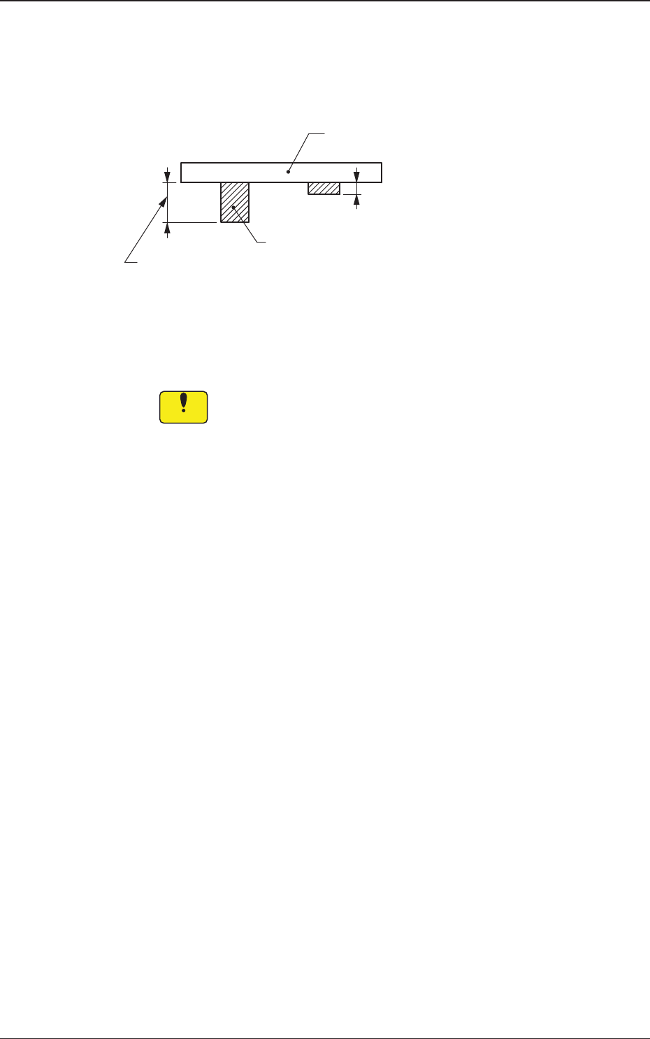
PCB Bottom [mm]
When PCBs with some components already mounted on the lower surfaces
(back) by the input machine are transferred to this machine, be sure to enter
the thickness of the highest component in the text box.
Tallest Previously Placed Component
PCB
Set this thickness in the text box.
Fig. 2B3-29
•
Data Input Range
0 to 13.000 (0 to 30.000)
Notice
(a) The set parameter is used to determine the position (elevation)
oftherstbackuptablewhenthePCBistransferredtothe
PCB positioning section.
(b) When components are placed previously and the main machine
is operated with "0.00" (no previously placed components) in
this text box, the support pins may interfere with some of the
previously placed components on the back of PCB while the
PCB is being transferred to the PCB positioning section.
(c) Theguresforthesettingrangeinbracketsshowthevalues
for the Y510mm Single Transfer Unit (Option).
1403-004
3.4 Control
2OM-1733
2-3-30
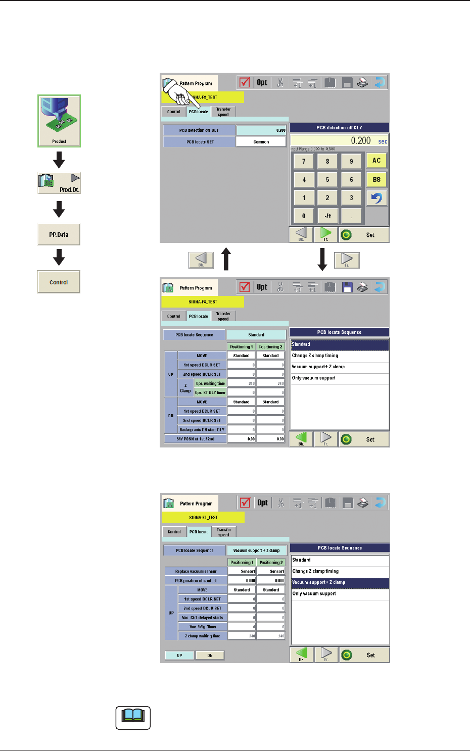
(D02) PCB locate
When the [PCB locate] tab is pressed in the "Control" window, the following
tab sheet appears.
Fig. 2B3-30
F2B3-31 Using vacuum support
Note
The vacuum support is an optional function.
Graphic
Development
1403-004
3.4 Control

2OM-1733
2-3-31
Note
The items in the following (a) and (b), are available depending on options
installed.
(a) The settings "(D02_03)", "(D02_04)", "(D02_05)" and "(D02_06)" are
available in the Y510 mm Single Transfer Unit (Option).
(b) The settings "(D02_07)", "(D02_08)", "(D02_09)" and "(D02_10)" are
used when the vacuum support (option) has been enabled.
(D02_01)
PCB detection off DLY
The time period from the PEC recognition to PCB release is set in this text
box.
(D02_02)
PCB locate SET
Common :
When selected, the PCB positioning is set commonly to the
machines in the line.
Individual :
When selected, the PCB positioning is set individually for each
machine in the line.
(D02_03)
PCB locate Sequence
The PCB positioning mode is set in this text box.
Standard
: When selected, the positioning operation for the
backup base is started at the same time with the
positioning operation for the Z-clamp.
Change Z clamp timing
: During the course of the positioning operation
for the back-up base, the Z-clamp movement is
started.
Only vacuum support
: When selected, the positioning is performed
using the vacuum support jig. (option)
(D02_04)
UP
Positioning 1, Positioning 2
MOVE
For the PCB positioning moving-up operation, select the mode from the
following mode items.
Normally, "Standard" is selected.
Standard
:
When selected, the PCB is moved up for positioning
based on the standard value set in the machine.
Low Speed 1
:
When selected, the operation speed is one step lower
than the standard value.
Low Speed 2
:
When selected, the operation speed is two step lower
than the standard value.
Low Speed 3
:
When selected, the operation speed is three step lower
than the standard value.
1403-004
3.4 Control