2OM-1733-005w_F8.pdf - 第64页
2OM-1733 1-2-4 (2) Feeder Status The current status of the feeder base is classied by color and displayed. How to understand the status of each color is as follows. Red : There are some feeders of which pick-up rate is …
2OM-1733
1-2-3
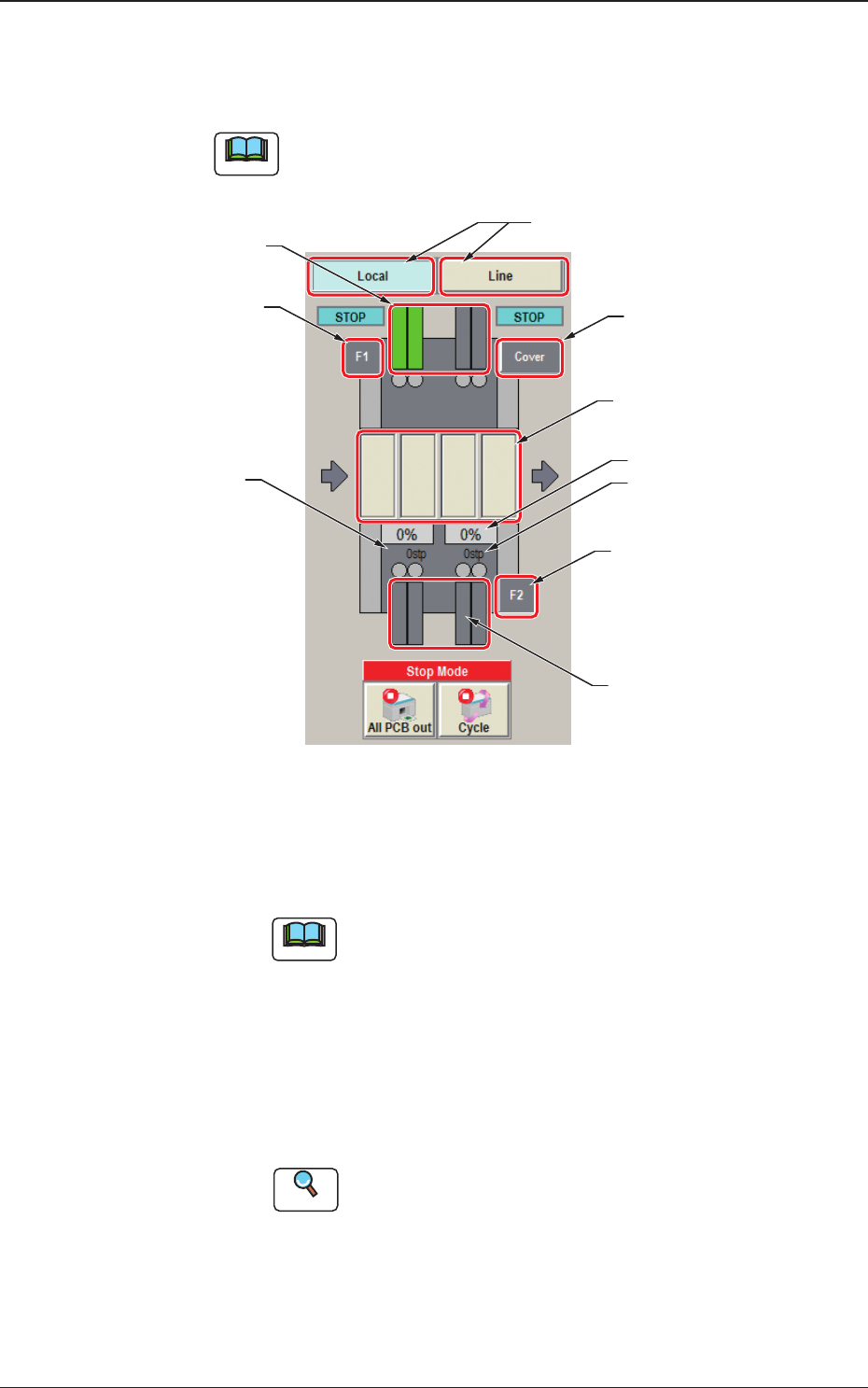
[2] Graphic Display Area
The graphic image of the PCB transfer and component input sections is
displayed in this area.
Note
The displayed contents will differ depending on selection of the options.
Feeder status (Pick-up Rate)
(2) 201 to 260
(Feeder Component Data)
PCB Process Status
(2) 101 to 160
Placement Step Count
(3)
(4)
(3)
(5)
(1)
Fig. 2A2-3 Graphic Display Area
(1) [Local] / [Line] Change Buttons
Using these buttons, the graphic display section is changed.
Note
When the line consists of a single unit, the line control change
button is not displayed.
[Local] Button
: When this button is pressed, the graphic image of
the single machine is displayed.
[Line] Button
: When this button is pressed, the graphic image of
the line is displayed.
The line start or line stop after the completed PCB
is discharged from the line, is performed.
Reference
Refer to "2.2 Line Window" for the details.
1212-002
2.1 Local Window
2OM-1733
1-2-4
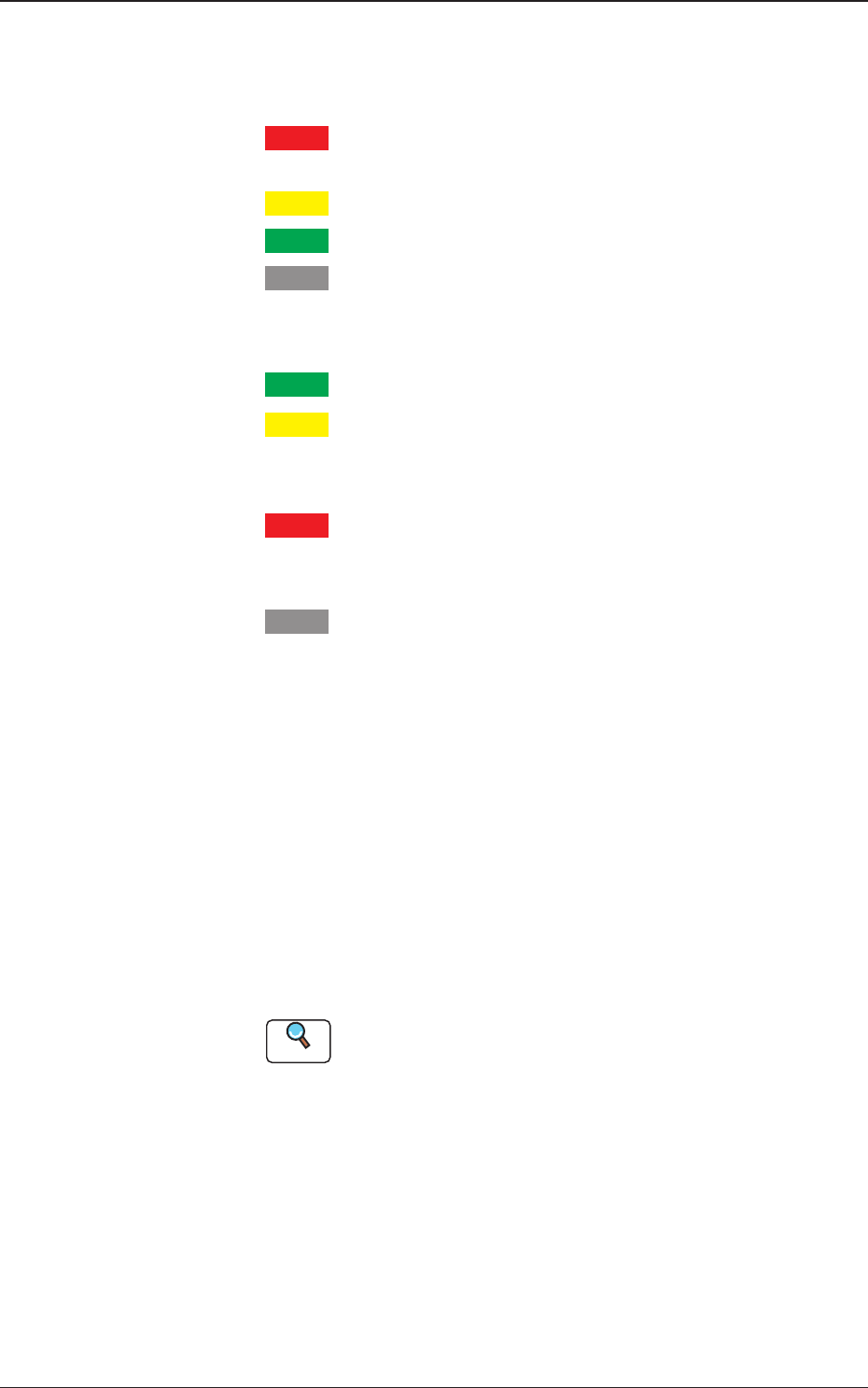
(2) Feeder Status
The current status of the feeder base is classied by color and
displayed. How to understand the status of each color is as follows.
Red
: There are some feeders of which pick-up rate is remarkably
dropped.
Yellow
: There are some feeders of which pick-up rate is dropped.
Green
: The pick-up condition is normal.
Gray
: It shows an unused feeder.
The component reload data for the corresponding feeder is displayed
in this section.
Green
: All feeders are normal.
Yellow
: There are some feeders for which the close attention is
required, such as the feeders with the component shortage
alarm.
Red
: There are some feeders which can not be used because of
component shortage or because the feeder has not been
installed.
Gray
: It shows an unused feeder.
(3) [F1], [F2] Buttons
When the [F1], or the [F2] button is pressed, the corresponding feeder
ready switch on the main body of the machine turns ON or OFF and
the feeder clamp holding bar is locked or unlocked. Note that the
feeder base cannot be moved up or down.
To move it up or down, the feeder ready switch on the main body of
the machine should be used.
(4) [Cover] Buttons
When this button is pressed, the open/close cover locking/unlocking
operation is performed.
Reference
Refer to "2.3.1 Feeder Ready Switches and 2.3.2 Cover Lock
Switches" in "Chapter 1 (Vol. 1)" for the cover lock switches on the
main body of the machine.
(5) Product PCB Status
The PCB during the component placement is displayed in dark green
and PCB in the stand-by condition is displayed in pale green.
1212-002
2.1 Local Window
2OM-1733
1-2-5
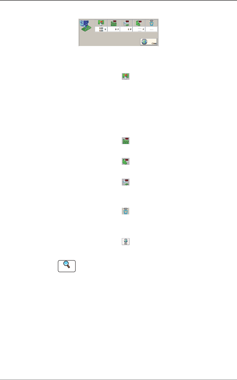
[3] Production Data
Fig. 2A2-4
"
Production Data
"
Window
PCB Process Time
: Displays the time required to nish one
PCB excluding the PCB in the middle of
process.
Displayed is the total time required
between the PCB receiving start and
the completion of the last component
placement.
Product PCB
: The number of produced unit PCBs is
displayed.
PCB Count
: The number of produced PCBs at present
is displayed.
Planned PCB Count
: The number of planned PCBs to be
produced is displayed.
Planned Production Finish Time
: In the case that the "Planned PCB Count"
has been set, the planned PCB production
nish time is displayed.
[Clear] Button
: When pressed, this button clears the
number of produced PCBs to "0"(zero).
Reference
Refer to "8. "PCB.CNT" window" in "Chapter 6" for how to use the "PCB
Count".
1212-002
2.1 Local Window