2OM-1733-005w_F8.pdf - 第299页
2OM-1733 6-4-9 1205-001 4.2 "Stkr .Area Edit" Window [7] [Cancel] Button When pressed, the editing operation is ended. Any arrangement parameter that has not been applied is cancelled.
2OM-1733
6-4-8
4.2 "Stkr.Area Edit" Window
[1] [2]
[3] [4] [5] [6] [7]
Fig. 2F4-9
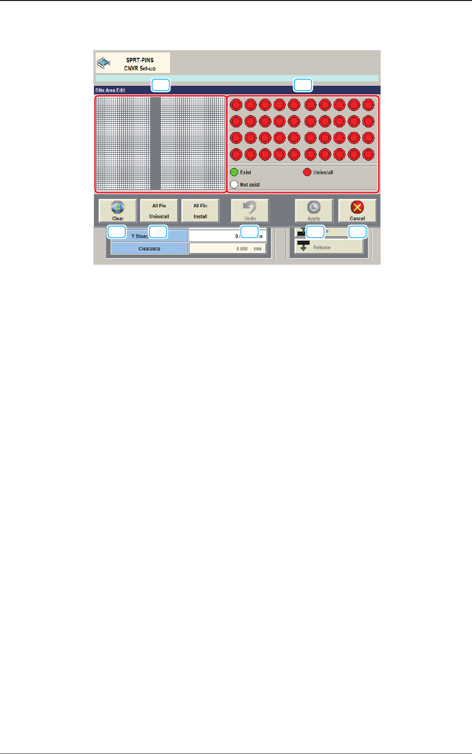
[1] PCB Support Pin Position Display Pane
The backup table is displayed as an image in this pane.
The arrangement condition of the PCB support pins is displayed.
[2] Stock Area Image Display Pane
The stock area for the PCB support pins is displayed as an image.
When any pin is clicked, "pin presence" and "pin absence" is toggled for the
corresponding pin.
Green
: Exist
Red
: Uninstall
White
: Not exist
[3] [Clear] Button
When pressed, the arrangement parameters for the PCB support pins
arranged on the backup table, is cleared.
[4] [All Pin Uninstall] Button
When pressed, the arrangement parameters for all the support pins for the
stock area, is changed to ones for "pin absence".
[5] [Undo] Button
When pressed, the parameters are returned to the original ones before the
change is applied.
[6] [Apply] Button
When pressed, the changed arrangement parameters in the stock area are
applied.
1212-002
4.2 "Stkr.Area Edit" Window

2OM-1733
6-4-91205-001
4.2 "Stkr.Area Edit" Window
[7] [Cancel] Button
When pressed, the editing operation is ended.
Any arrangement parameter that has not been applied is cancelled.
2OM-1733
6-4-10
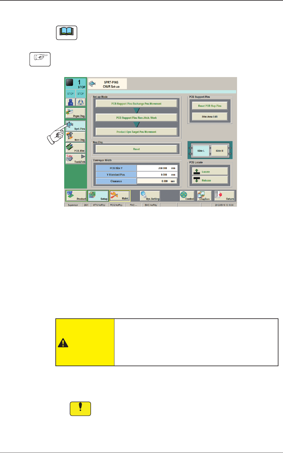
4.2.1 Stocker Area Edit Procedure
Note
This section is described based on the front reference and PCB ow direction
from left to right.
Procedure
(1) Press [Sprt-Pins] button in the "Setup" main menu bar to display the
following window.
Fig. 2F4-10
(2) Press the [PCB Support Pins Exchange Pos. Movement] button and within
10 seconds, press the [START] button on the operation panel.
(The head will retract and the conveyor width becomes the maximum one.)
(3) Press the cover lock switch and turn off the light on the switch.
(The transparent covers are unlocked).
(4) Open the transparent covers.
CAUTION
The load power to the motors, etc., is turned OFF
but the setup operation must be performed carefully
when you put your hand inside the machine. Avoid
handandngerinjuries.
(5) Insert the PCB support pins directly into each hole in the stock area on the
backup table.
Notice
In the case that any operation is to be performed on the backup
table, when any strong pressure is applied to the backup table such
as touching the backup table with your hand to support your body
or putting an object on the backup table, it might be deformed. Take
the greatest care.
1212-002
4.2 "Stkr.Area Edit" Window