2OM-1733-005w_F8.pdf - 第171页
2OM-1733 2-3-37 (D03_01) T ransportation speed SET Common : When selected, the transfer speed is set commonly to the machines in the line. Individual : When selected, the transfer speed is set individually for each machi…
2OM-1733
2-3-36
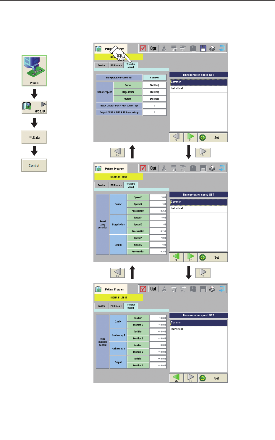
(D03) Transfer speed
When the [Transfer Speed] tab is pressed in the "Control"window, the
following tab sheet appears.
Fig. 2B3-32
Graphic
Development
1212-002
3.4 Control

2OM-1733
2-3-37
(D03_01)
Transportation speed SET
Common :
When selected, the transfer speed is set commonly to the
machines in the line.
Individual :
When selected, the transfer speed is set individually for each
machine in the line.
(D03_02)
Transfer speed
Carrier, Stage inside, Output
Select the PCB transfer speed from the following items.
Std(Max)
: When selected, the PCB is transferred at the standard speed.
-20%
: When selected, the PCB is transferred at the speed 20%
lower than the standard.
-40%
: When selected, the PCB is transferred at the speed 40%
lower than the standard.
-60%
: When selected, the PCB is transferred at the speed 60%
lower than the standard.
-80%
: When selected, the PCB is transferred at the speed 80%
lower than the standard.
Value Set
: When selected, any speed level is set freely for the PCB
transfer.
(D03_03)
Avoid comp deviation
Carrier, Stage inside, Output
The following items are set for "Reload", "Stage Inside" and "Discharge".
Speed 1 [mm/sec]
The PCB is transferred at the specied speed.
Speed 2 [mm/sec]
The PCB transferred at the Speed 1, is detected using the speed reduction
sensor and the speed is reduced to the "Speed 2"specied here in this text
box.
Acceleration [G]
The acceleration to reach the speed specied in "Speed 1"is set in this text
box.
1403-004
3.4 Control
2OM-1733
2-3-38
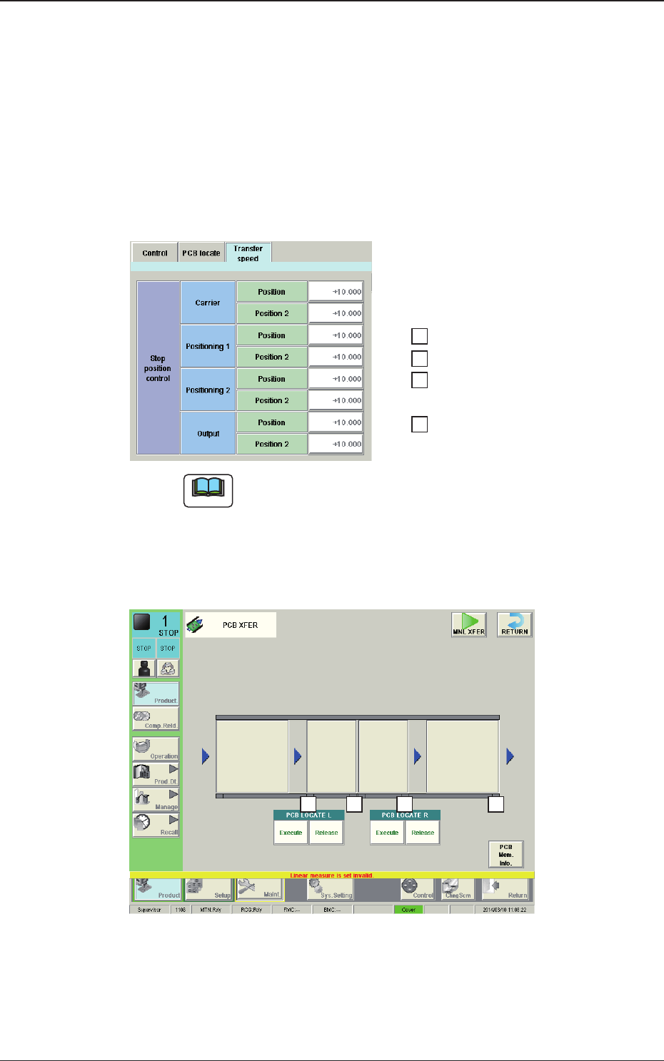
(D03_04)
Stop position control
Carrier, Positioning 1, Positioning 2, Output
The following items are set for "Reload", "Positioning 1", "Center",
"Positioning 2"and "Discharge".
Position [mm]
The distance from the position of the PCB detected using the stop sensor
to the PCB stop position, is set in this text box.
……… 1
……… 2
……… 3
……… 4
4 3
1
2
Fig. 2B3-32-1
1403-004
3.4 Control
Note
The relationship between the settings and the PCB stop positions is as
follows.
When any of the stop positions "1" through "4" shown in the upper
window in the gure, is changed, the distance from the PCB detection
in the positions "1" through "4" in the lower window in the following
gure, to the PCB stop position, is changed accordingly.