2OM-1733-005w_F8.pdf - 第190页
2OM-1733 2-3-56 (G04_03) Z=theta [deg] Set an angle of each pattern. Keep the angle of the reference pattern as "0 deg". In the gure below, "Pattern 1" is regarded as a reference one. N 0 : The cente…
2OM-1733
2-3-55
(G04_02)
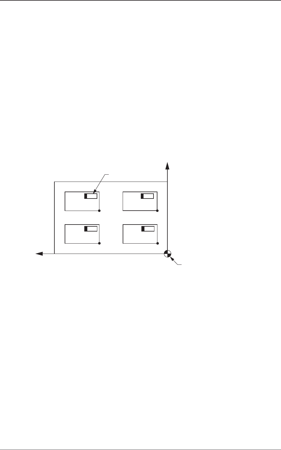
X [mm] and Y [mm]
Set the coordinates of each pattern origin (O01 through On) based on the
placement coordinate reference (N0). A pattern origin refers to the reference
coordinates of a repetitive pattern.
The position reference should be located at the corner position on the same
side of the placement position reference (N0), assuming the Z-data described
in the next (F04_03) as "0 degree".
N
0
:
The center of is the placement coordinate reference.
O
01
:
Pattern Origin of Pattern 1
O
02
:
Pattern Origin of Pattern 2
O
03
:
Pattern Origin of Pattern 3
O
04
:
Pattern Origin of Pattern 4
O04
O03
O02
O01
X
Y
Placement Coordinate
Reference (No)
Component
Pattern 4 Pattern 3
Pattern 2 Pattern 1
Fig. F2B3-48
1212-001
3.7 Placement
2OM-1733
2-3-56
(G04_03)
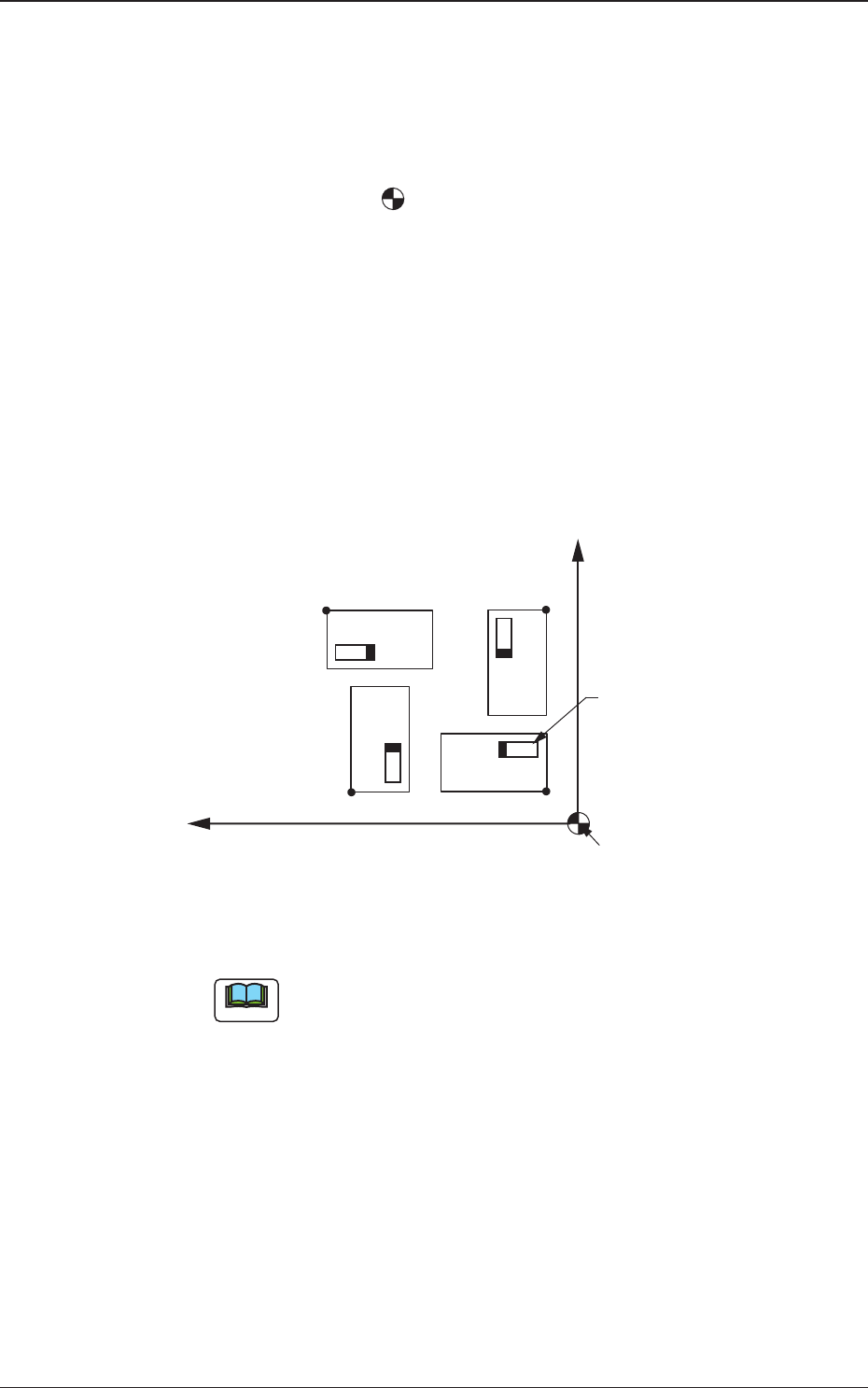
Z=theta [deg]
Set an angle of each pattern. Keep the angle of the reference pattern as "0
deg".
In the gure below, "Pattern 1" is regarded as a reference one.
N
0
:
The center of
is the placement coordinate reference.
O
01
:
Pattern Origin of Pattern 1
O
02
:
Pattern Origin of Pattern 2
O
03
:
Pattern Origin of Pattern 3
O
04
:
Pattern Origin of Pattern 4
Pattern 1 :
0 deg
Pattern 2 :
90 deg
Pattern 3 :
180 deg
Pattern 4 :
270 deg
X
O
03
O02
O01
O04
Y
Placement Coordinate
Reference (No)
Component
Pattern 4
Pattern 3
Pattern 2
Pattern 1
Fig. 2B3-49 Example of Repetitive Patterns
Note
A numerical value must be entered in increments of 90 deg. Otherwise, an
error will occur.
1212-002
3.7 Placement
2OM-1733
2-3-57
(G04_04)
H [mm]
The height for each individual patterns (unit PCBs) can be corrected.
Note
When a parameter is set as "H" data in the last line (last step No.), it
becomes invalid because "E" is set in the "C (Control Command)" text
box.
(G04_05)
C
Enter some of the following control commands.
Note
If a control command other than the following ones is used, the step
becomes invalid.
- (hyphen)
: This command handles the steps as those for component
placement.
S
: This command invalidates the steps specied as those for
component placement.
C
: This command invalidates the steps specied as those for
component placement.
Note
As for dispensers, these steps become valid.
D
: This command handles the steps as those for component
placement.
Note
As for dispensers, these steps become invalid.
E
: When placement data (O) is not created, this shows the end of
the steps in the placement data (P).
Note
Conrm that "0" (zero) is set in the "X [mm]", "Y [mm]", and "Z=theta
[deg]" text boxes of the last line (last step No.) and set "E".
(G04_06)
Comment
Set a comment for each step No. Alphanumeric characters and symbols can
be used. Up to 32 characters (alphanumerics and marks) can be used.
Note
The automatic operation is not affected by these comments.
1204-001
3.7 Placement