2OM-1733-005w_F8.pdf - 第79页
2OM-1733 1-4-3 [3] Cancel Run When the Cancel Run button is pressed, the "Pause" condition is cancelled and the machine is turned to the "STOP" mode. Note When the machine is set in the "P AUSE&q…
2OM-1733
1-4-2
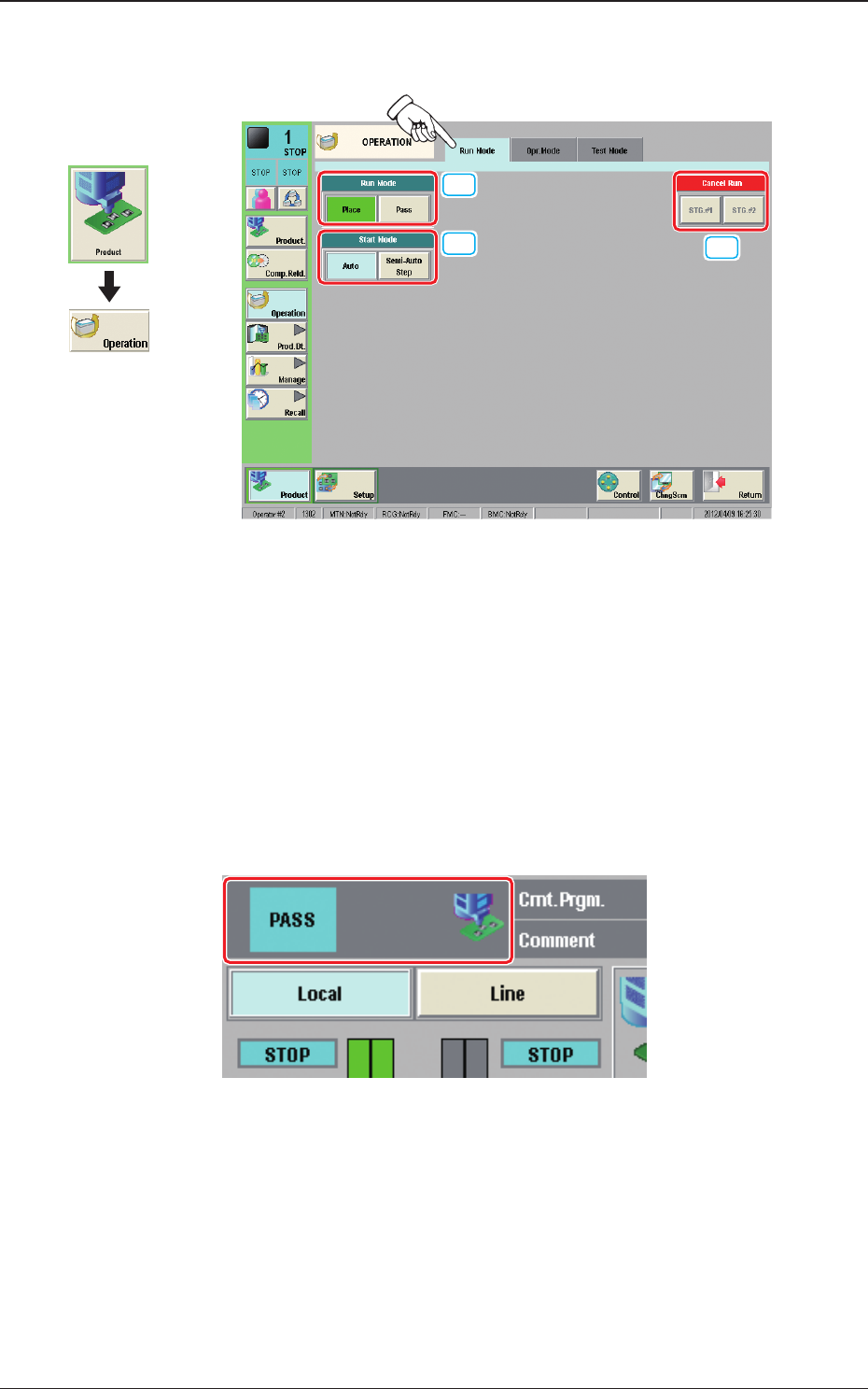
4.1 "Run Mode" Tab Sheet
[3]
[1]
[2]
Fig. 2A4-2
[1] "Run Mode" Selection Buttons
Press either one of the following buttons to select the desired run mode.
[Place] Button
: Select this button to set the machine in the "PLACE
(Automatic Operation)" mode.
[Pass] Button
: Select this button to set the machine in the "PASS" mode.
In the case that the pass operation has been setup, "PASS" is displayed in the
"Status Indicator" on the upper area of the "Product" window.
Status Indicator
Fig. 2A4-3
[2] "Start Mode" Selection Buttons
Using the following buttons, the start mode is setup.
[Auto] Button
: Select this button to start up the machine
automatically.
[1 Comp Placement] Button
: Select this button to stop the machine after
the designated single component has been
placed.
Graphic
Development
1212-002
4.1 "Run Mode" Tab Sheet

2OM-1733
1-4-3
[3] Cancel Run
When the Cancel Run button is pressed, the "Pause" condition is cancelled
and the machine is turned to the "STOP" mode.
Note
When the machine is set in the "PAUSE" mode by pressing the [STOP]
button on the operation panel during the automatic operation, etc., the
Cancel Run button becomes available.
1212-002
4.1 "Run Mode" Tab Sheet
2OM-1733
1-4-4
•
Automatic Operation Start after the Component Reload or for the Test
Operation
Setup the Starting Mode and Starting Step No. and press the [START] button
on the operation panel to start up the automatic operation.
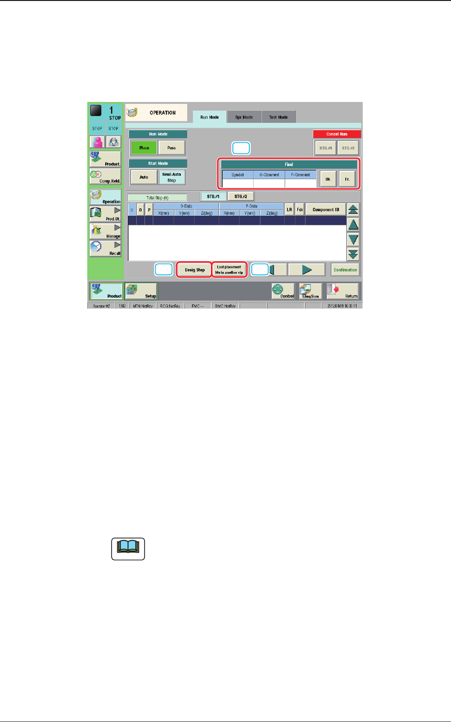
When the [Semi-Auto Step] button is pressed, the following window appears.
[1]
[2] [3]
Fig. 2A4-4 "Run Mode" Tab Sheets
[1] Find
Enter characters in the text boxes for "Symbol", "O-Data Comment" and
"P-Data Comment" and press the [Forward] or [Backward] button to search
the parameter successively.
[2] Desig Step
When the operation is to be started from the desired step No. in the pattern
program, setup the starting step No.
The background color of the designated step turns blue.
Starting Step Nos. U, O, and P can be designated sequentially, using the
entry window that can be opened by pressing the [Desig Step] button.
Note
In normal cases, the starting step Nos. are displayed in the order of actual
component placement.
By pressing the [O] or the [P] button, the steps can be re-arranged in the
ascending order.
Even when the step Nos. are rearranged, the component placement order is
not changed.
[3] Last placement Mv.to another stp
When this button is pressed, the position is moved to the nal placement
step.
1212-002
4.1 "Run Mode" Tab Sheet