2OM-1733-005w_F8.pdf - 第160页
2OM-1733 2-3-26 3.4 Control (D01) Control When the [Control] tab is pressed in the "Control" window, the following tab sheet appears. Fig. 2B3-25 (D01_01) Placement mode "Product" or "Pass" …
2OM-1733
2-3-25
(C05_05)
M-X, M-Y
Using these selection boxes, the support pin placement coordinates (M-X,
M-Y) are setup.
Coord X, Coord Y
The set support pin coordinates are displayed in these data boxes.
•
Data Input Range
Input
M-X
: 1 to 26
M-Y
: 1 to 24 (1 to 50)
Output
M-X
: 1 to 26
M-Y
: 1 to 24 (1 to 50)
Note
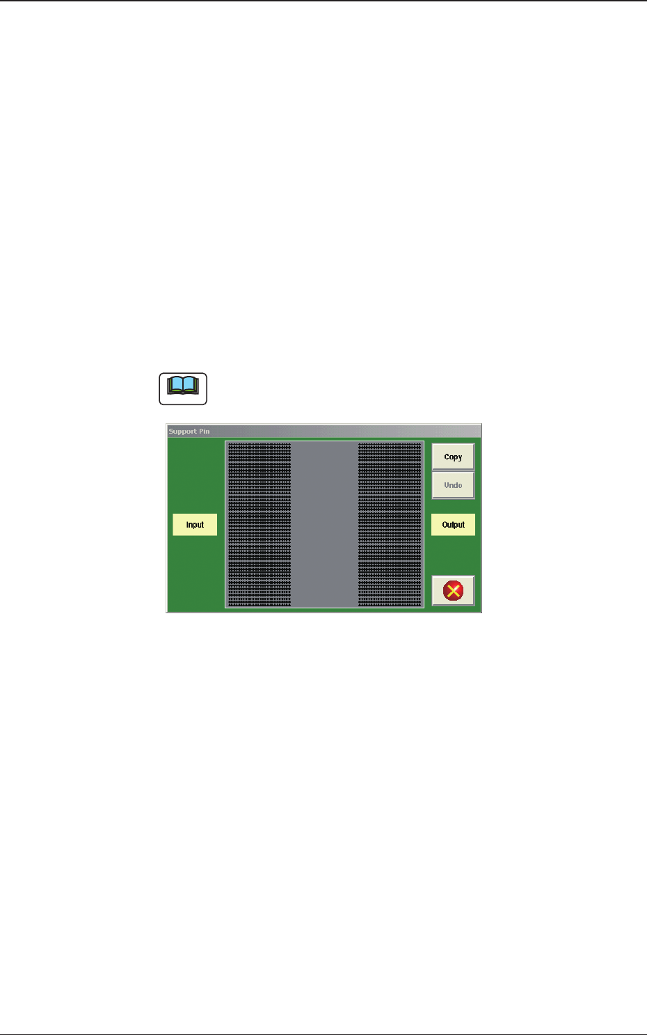
(a) When the [Pin] button is pressed, the "Support Pin" dialogue box is
opened and the support pin positions can be checked.
Fig. 2B3-24
(b) When the [Clear] button is pressed, the support pins with the selected
Nos. are cleared.
(c) The gures for the setting range in brackets show the values for the
Y510mm Single Transfer Unit (Option).
1403-004
3.3 Operation
2OM-1733
2-3-26
3.4 Control
(D01)
Control
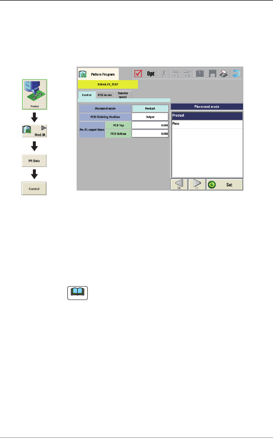
When the [Control] tab is pressed in the "Control" window, the following tab
sheet appears.
Fig. 2B3-25
(D01_01)
Placement mode
"Product" or "Pass" is selected for the placement mode in this pane.
Normally, "Product" is selected.
Product
: When selected, the placement operation is performed.
Pass
: When selected, the PCB is passed without placement.
Note
When the pattern program set to "Pass", is setup on the Pattern Program
Data, the vacuum pump is automatically turned OFF.
Graphic
Development
1212-002
3.4 Control
2OM-1733
2-3-27
(D01_02)
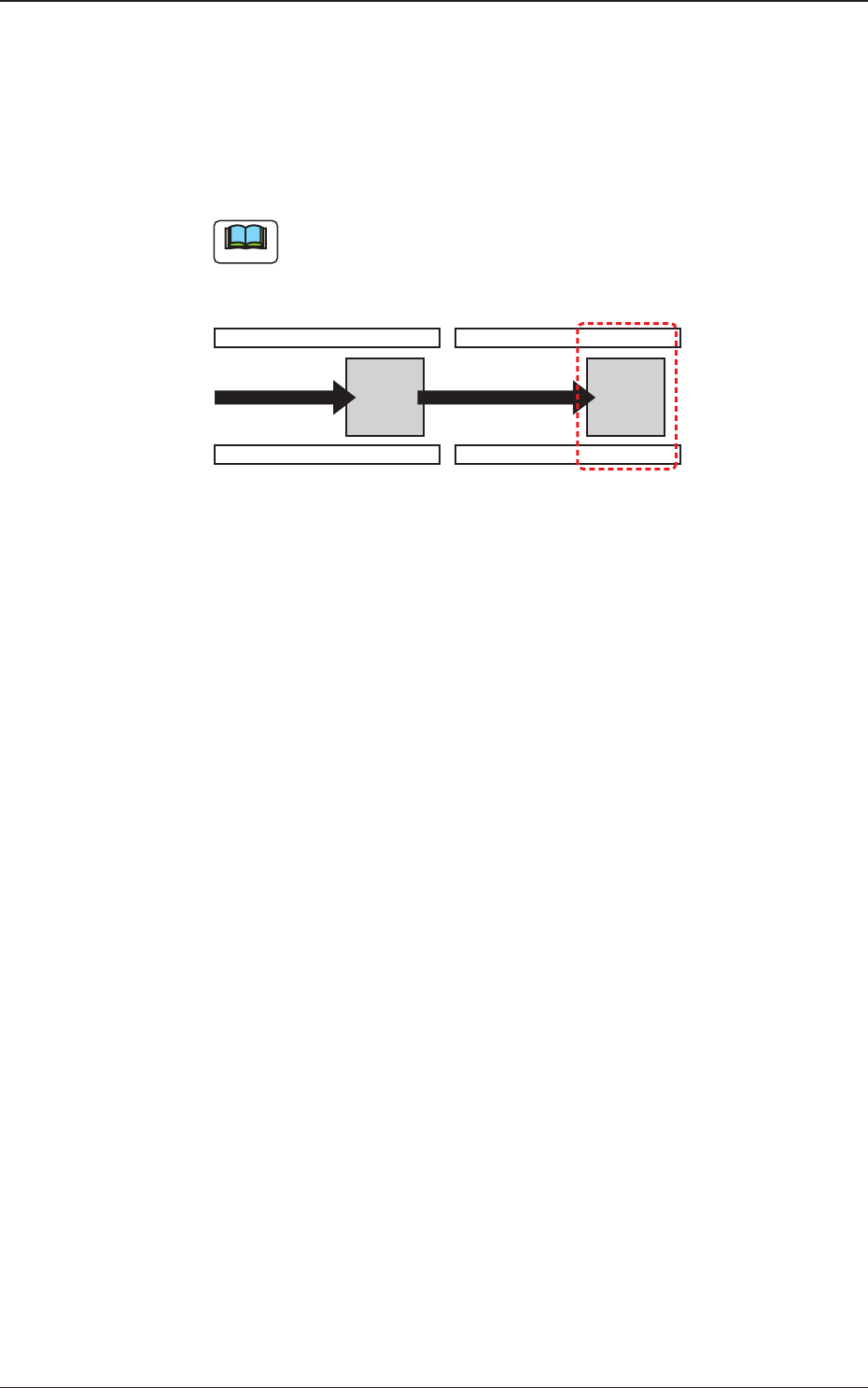
PCB Finishing Position
The PCB Finishing Position is selected in this text box.
Output
The component placement is performed on the downstream side.
Note
The PCB nishing position should be xed on the downstream side.
Production Position
Fig. 2B3-26
1212-002
3.4 Control