2OM-1733-005w_F8.pdf - 第158页
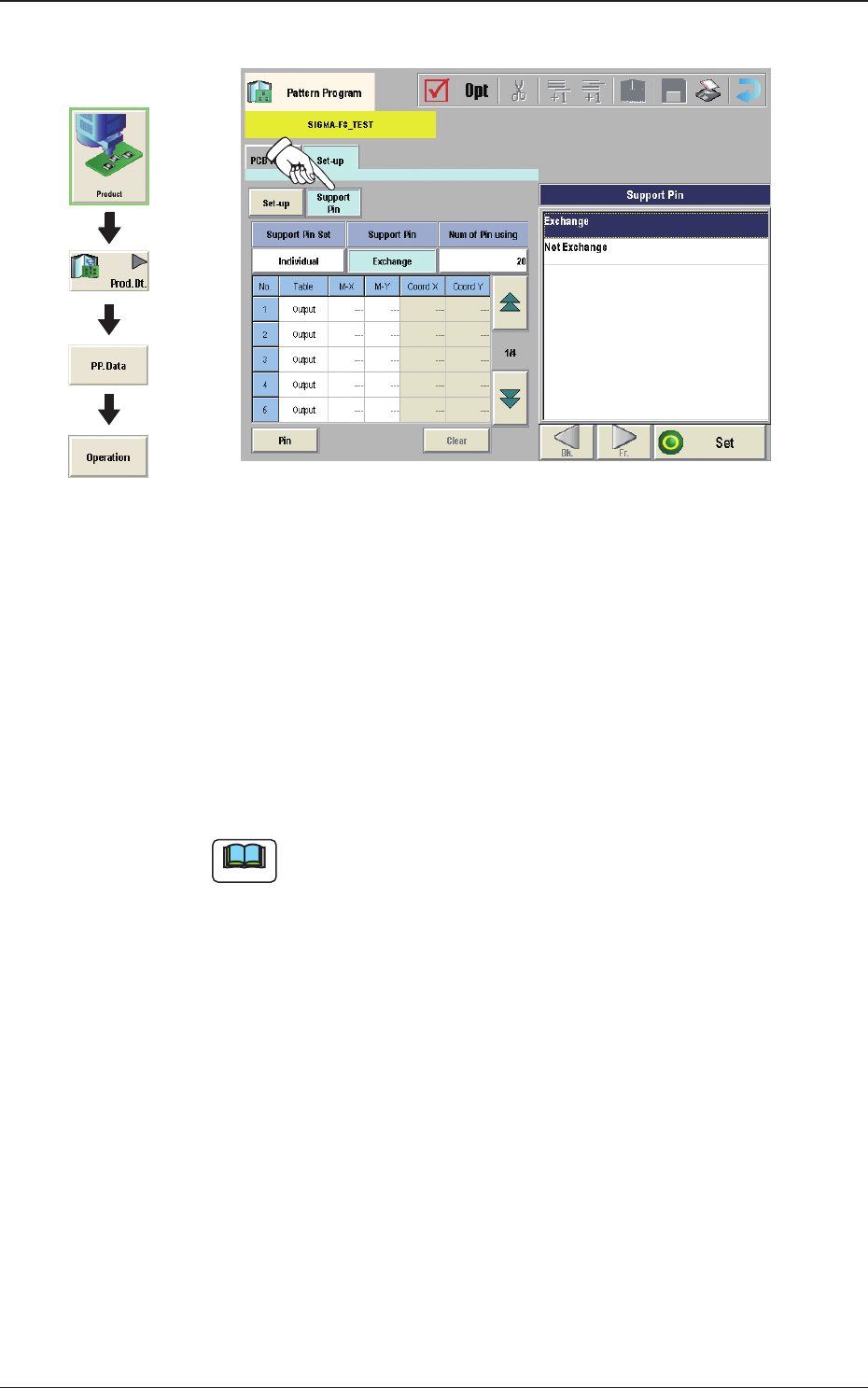
2OM-1733 2-3-24 (C05_02) Support Pin Using this selection button, it is set whether or not the support pins are setup automatically in the pattern program change operation. (C05_03) Num of Pin using The number of pins to…
2OM-1733
2-3-23
(C05) Support Pin
Fig. 2B3-23
(C05_01)
Support Pin Set
Using the selection buttons, select "Common" or "Individual" to set.
Common
When selected, it is set as the line common data.
Individual
When selected, it is set as the machine individual data.
Note
When the line consists of two or more machines and the line common data
is set up, the data is shared by all the machines (SIGMA-F8) in the line.
However, when the machine individual data is set up, each machine has its
own individual data to be set.
Graphic
Development
1212-002
3.3 Operation

2OM-1733
2-3-24
(C05_02)
Support Pin
Using this selection button, it is set whether or not the support pins are setup
automatically in the pattern program change operation.
(C05_03)
Num of Pin using
The number of pins to be used in the automatic operation is set in this
selection box.
•
Data Input Range
1 to 40 pins
(C05_04)
Table
Using this selection box, it is set that the backup base where the support pins
are placed, is in the output or input.
1212-002
3.3 Operation
2OM-1733
2-3-25
(C05_05)
M-X, M-Y
Using these selection boxes, the support pin placement coordinates (M-X,
M-Y) are setup.
Coord X, Coord Y
The set support pin coordinates are displayed in these data boxes.
•
Data Input Range
Input
M-X
: 1 to 26
M-Y
: 1 to 24 (1 to 50)
Output
M-X
: 1 to 26
M-Y
: 1 to 24 (1 to 50)
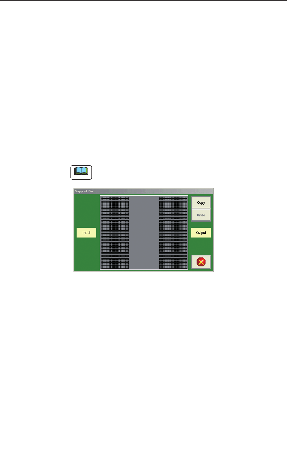
Note
(a) When the [Pin] button is pressed, the "Support Pin" dialogue box is
opened and the support pin positions can be checked.
Fig. 2B3-24
(b) When the [Clear] button is pressed, the support pins with the selected
Nos. are cleared.
(c) The gures for the setting range in brackets show the values for the
Y510mm Single Transfer Unit (Option).
1403-004
3.3 Operation