2OM-1733-005w_F8.pdf - 第338页
2OM-1733 6-7-20 [5] [Move] Button Using this button, the beam is moved to the set position. [6] [Manual Alignment] Button Using this button, the window where the recognition position setup using the manual alignment oper…
2OM-1733
6-7-19
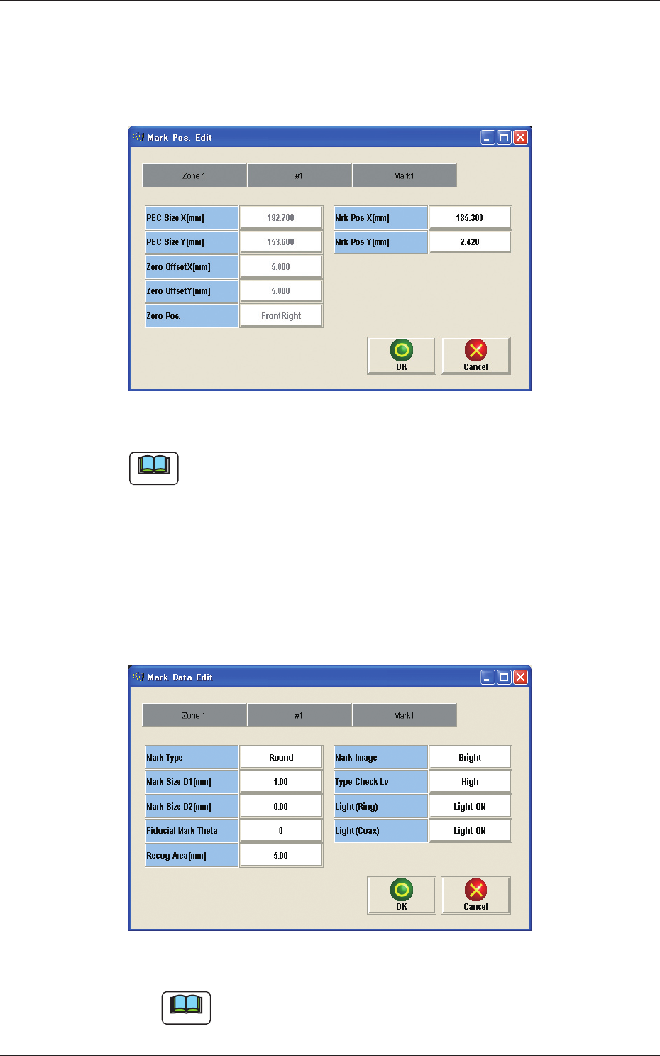
[3] [Mark Pos Edit] Button
Using this button, the PEC recognition mark position is setup.
Each item is shows as a button and when each button is pressed, the
corresponding data set window appears.
Fig. 2F7-15
Note
(a) When the pattern program has been setup, the parameters for the [PEC Size
X[mm]], [PEC Size Y[mm]] and [Y arrange Pos] are automatically
set.
(b) When the settings have been performed in the "Cmt PP Data Setting"
window, the [Mrk Pos X[mm]] and [Mark Pos Y[mm]] also have already
been setup.
[4] [Mark Data Edit] Button
Press each button to set the PEC recognition mark.
Fig. 2F7-16
Note
When the settings have been performed in the "Cmt PP Data Setting"
window, the PEC recognition mark data has already been setup
1212-001
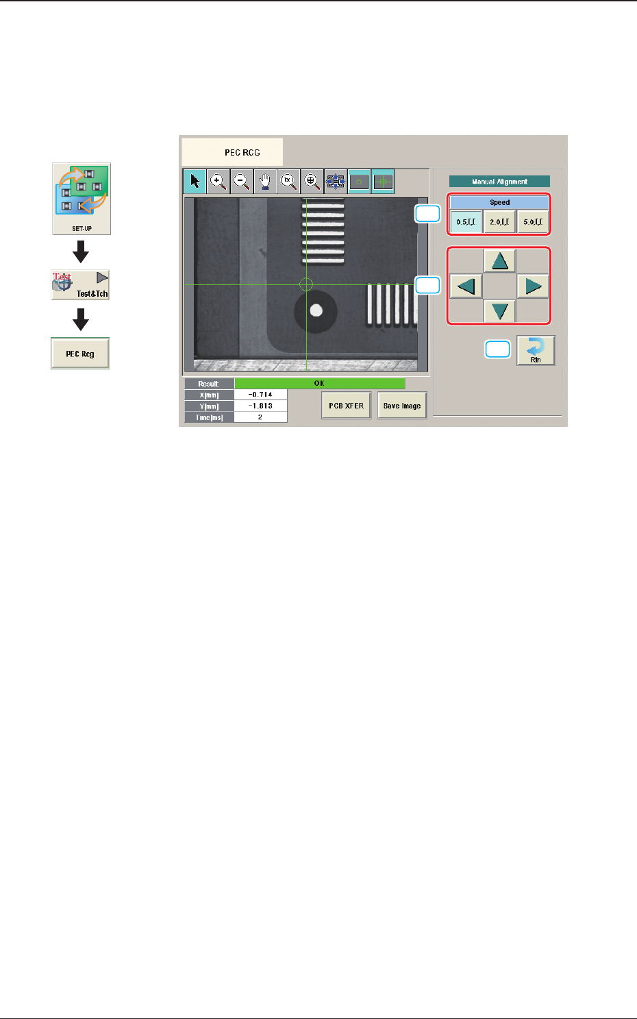
7.3 "PEC RCG" Test Window

2OM-1733
6-7-20
[5] [Move] Button
Using this button, the beam is moved to the set position.
[6] [Manual Alignment] Button
Using this button, the window where the recognition position setup using the
manual alignment operation, is opened.
[7] [PEC Recog] Button
When this button is pressed, the PEC recognition test is prepared.
[8] Result:
In this pane, the PEC recognition test results are displayed.
[9] [PCB XFER] Button
When this button is pressed, the "PCB Transfer" window appears.
[10] [Save Image] Button
When this button is pressed, the "Image Save" window appears.
This window is used to save the test results.
[11] [Re-Recognition] Button
After pressing this button, the recognition image is touched in the "Manual
Alignment" window to re-recognize the marks.
1212-001
7.3 "PEC RCG" Test Window
2OM-1733
6-7-21
7.3.1 Manual Alignment Operation
The PEC recognition position is located using the manual alignment operation.
When the [Manual Alignment] button is pressed after the [Move] button is pressed
on the "PEC RCG" test window, the "Manual Alignment" window appears.
[1]
[2]
[3]
Fig. 2F7-17
[1] [Speed] Button
The beam movement speed in the manual alignment operation is selected
from the following items.
[0.5 mm] Button, [2.0 mm] Button, [5.0 mm] Button
[2] Manual Alignment Operation
When pressed, the beam is moved at the speed selected in "[1] Speed Setup"
in the arrow direction.
[3] [Rtn] Button
When pressed, the "PCB Test" window is returned.
1212-001
7.3 "PEC RCG" Test Window
Graphic
Development