2OM-1733-005w_F8.pdf - 第66页
2OM-1733 1-2-6 1212-003 2.1 Local Window [4] Data Display Section The production data, component reload data and component handling rate data parameters are displayed in this section. Each data display is changed using t…
2OM-1733
1-2-5
[3] Production Data
Fig. 2A2-4
"
Production Data
"
Window
PCB Process Time
: Displays the time required to nish one
PCB excluding the PCB in the middle of
process.
Displayed is the total time required
between the PCB receiving start and
the completion of the last component
placement.
Product PCB
: The number of produced unit PCBs is
displayed.
PCB Count
: The number of produced PCBs at present
is displayed.
Planned PCB Count
: The number of planned PCBs to be
produced is displayed.
Planned Production Finish Time
: In the case that the "Planned PCB Count"
has been set, the planned PCB production
nish time is displayed.
[Clear] Button
: When pressed, this button clears the
number of produced PCBs to "0"(zero).
Reference
Refer to "8. "PCB.CNT" window" in "Chapter 6" for how to use the "PCB
Count".
1212-002
2.1 Local Window
2OM-1733
1-2-61212-003
2.1 Local Window
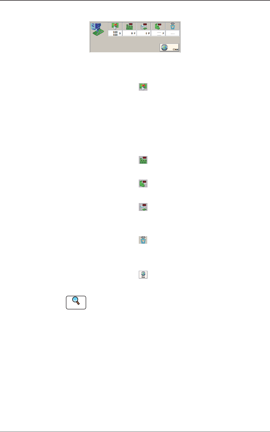
[4] Data Display Section
The production data, component reload data and component handling rate
data parameters are displayed in this section. Each data display is changed
using the button on the lower right of the display section.
Production Data
When the display change button (left) is pressed, this window appears.
Fig. 2A2-5 "Production Data" Window
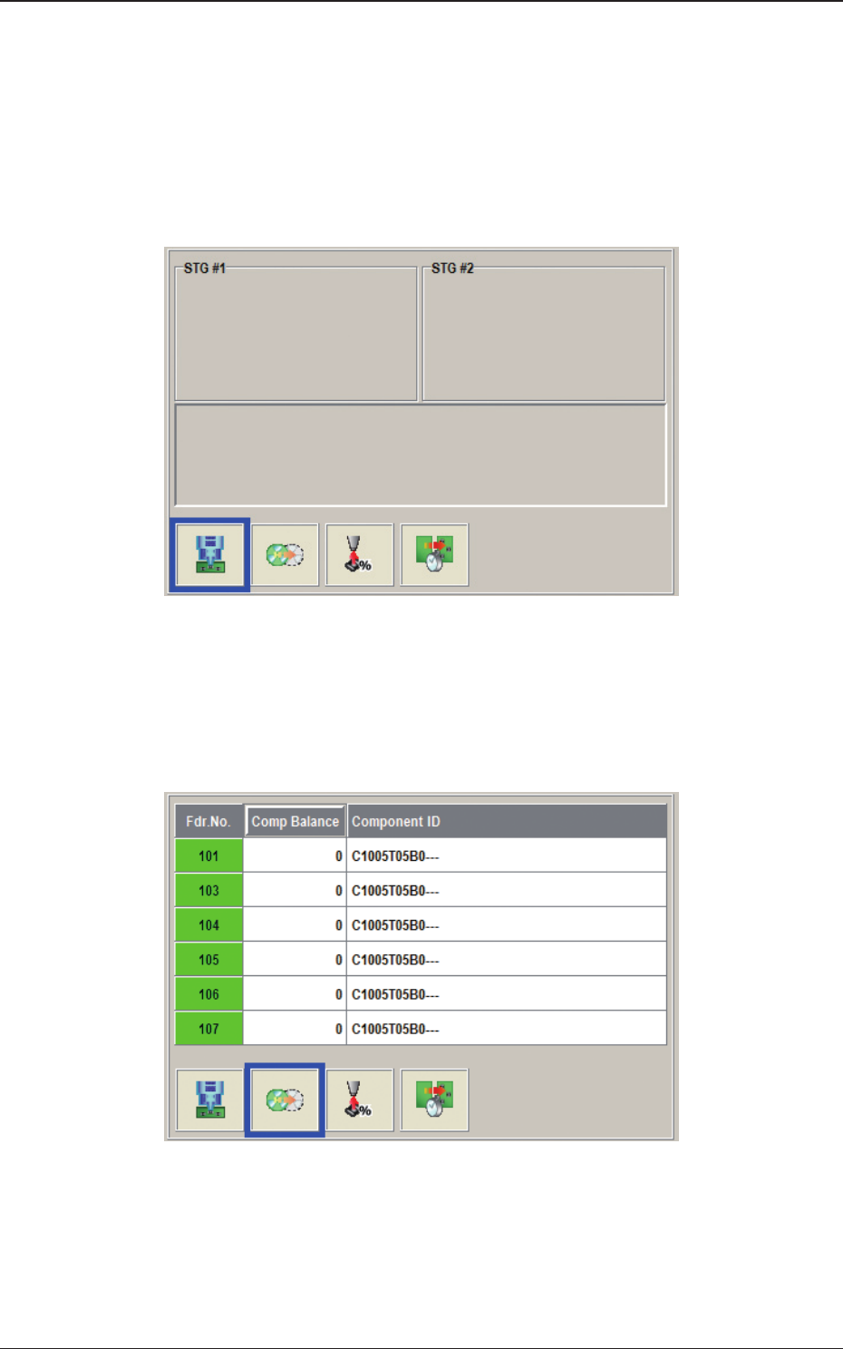
Feeder Reload Data
The data of the feeder where the component replenishment is required, is
displayed.
Fig. 2A2-6
"
Feeder Reload Data
"
Window
2OM-1733
1-2-7
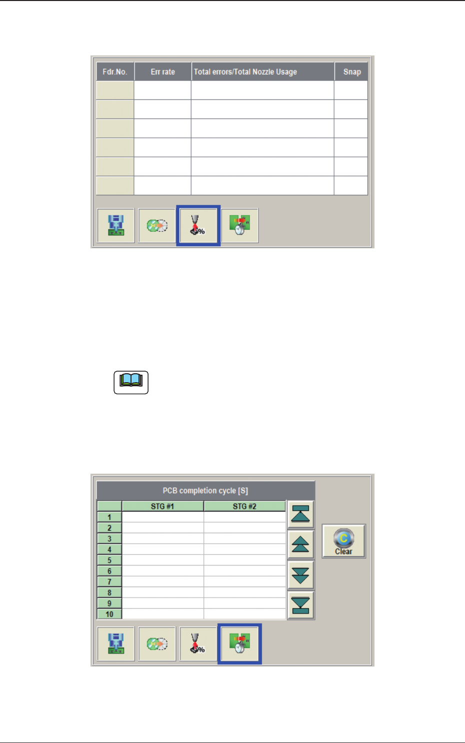
Component Handling Rate Data
The data of the feeder where the pick-up rate has been dropped, is displayed.
Fig. 2A2-7
"
Component Handling Rate Data
"
Window
PCB completion cycle
Max. 500 items of the measured nishing interval (interval between the
previous PCB and the current PCB at the nal step completion) are displayed
from the newest.
Note
(a) Because the interval cannot be measured before the second PCB is
completed, "---" is displayed at the rst PCB nished time.
(b) In the case that the placement status becomes "Stopping" or "Pause",
the measurement of the PCB is stopped and "---" is displayed.
(c) The history is automatically saved in "D:\mdata\MachDt\PcbInt.csy"
when the whole status becomes "Stopping".
Fig. 2A2-8 "PCB completion cycle" Window
1212-003
2.1 Local Window