OM-1068-001.pdf - 第102页
5. Preparation and Confirmation before Operation Tg0252-PM-SO 5.2.2.4 Partition Plate Removal Procedure in Even Steps • When a component of 1 1.5 mm or more in height is placed on the tray t1or t2, the partition plate (e…
5. Preparation and Confirmation before Operation
Tg0252-PM-SO
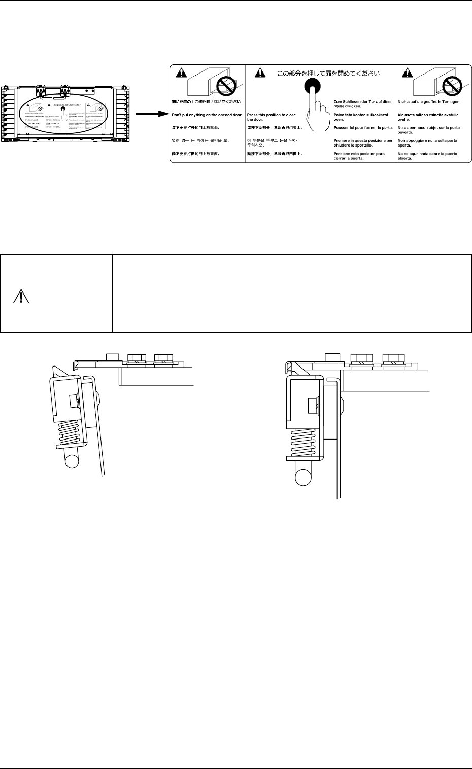
(4) Press the black circle point shown in the label in Fig. 1.21-2 to
close the magazine door.
(5) Confirm that the magazine door is latched.
(Fig. 1.21-4)
Fig. 1.21-1
Fig. 1.21-2
If the magazine door is closed roughly, components might be bumped
out of the tray. Close it gently and securely.
If the magazine door is not latched securely, it may open suddenly dur-
ing operation (while the machine is running), causing some damage to
the machine.
CAUTION
0112-003 Chapter 1 2-18
5.2.2.3 Pallet Detachment from Magazine
(1) Push both handles of the magazine door fixture down in direction shown
by an arrow A and release the lock of the magazine door. (Fig. 1.19-1 and
Fig. 1.19-2, Arrow A)
(2) Open the magazine door.
(Fig. 1.19-3 Arrow B)
(3) Pull out the pallet to be detached.
Fig. 1.21-3 Unlatched Magazine Door
Fixture
Fig. 1.21-4 Latched Magazine Door Fixture
5. Preparation and Confirmation before Operation
Tg0252-PM-SO
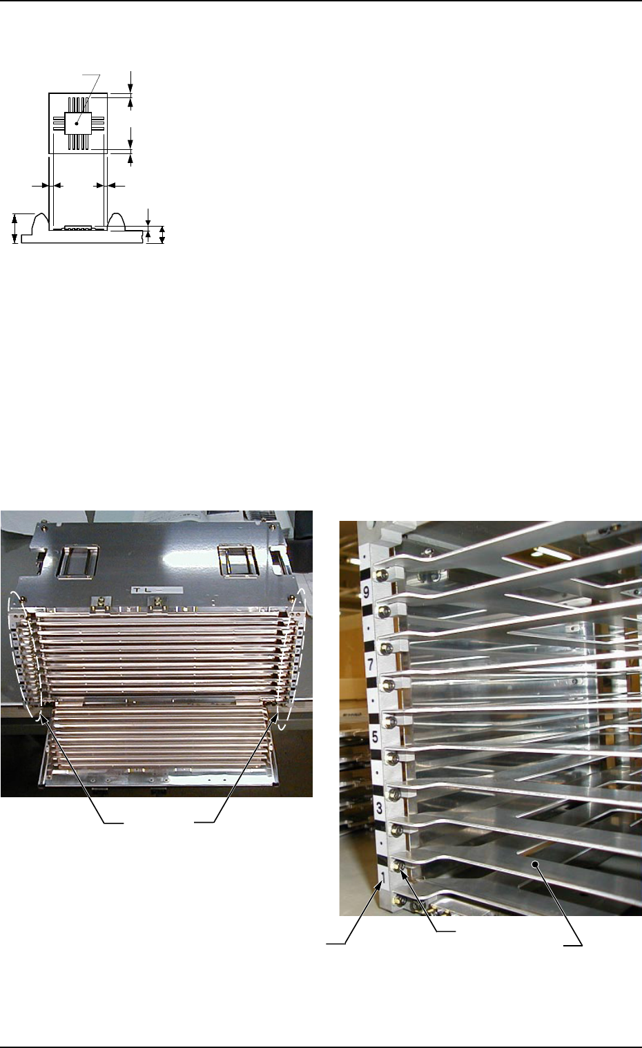
5.2.2.4 Partition Plate Removal Procedure in Even Steps
• When a component of 11.5 mm or more in height is placed on the
tray t1or t2, the partition plate (even steps) should be detached to
avoid interference of the partition plate with the component.
(1) Pull the grip of the magazine door fixture down in the di-
rection of Arrow A to unlatch the magazine door. (Figs.
1.19-1 and 1.19-2 Arrow A)
(2) Open the magazine door. (Fig. 1.19-3 Arrow B)
(3) Remove the bolts fixing the partition plate and remove the
plate.
Notes : (a) When the partition plate is removed, confirm
the step No. and remove the partition plate
only at the even steps. If the partition plate
at the odd stage is removed and the pallet is
set there, the pallet can’t be drawn out from
the magazine during operation.
(b) The partition plate and bolts, which have
been removed will be used when the parti-
tion plate is installed again. Set aside with
care. Also, handle the partition plate care-
fully because it is easily deformed.
Enlarged Figure (Same condition on the right side)
Fig. 1.22
Fig. 1.23
Right
Side
Left
Side
Bolt
Step No.
Partition Plate
SS
S
t
Component
S
t
1
t
2
0112-004 Chapter 1 2-19
5. Preparation and Confirmation before Operation
Tg0252-PM-SO
5.2.2.5 Partition Plate Installation Procedure in Even Steps
(1) Pull the grip of the magazine door fixture down in the direction of Arrow
A to unlatch the magazine door. (Figs. 1.19-1 and 1.19-2 Arrow A)
(2) Open the magazine door. (Fig. 1.19-3 Arrow B)
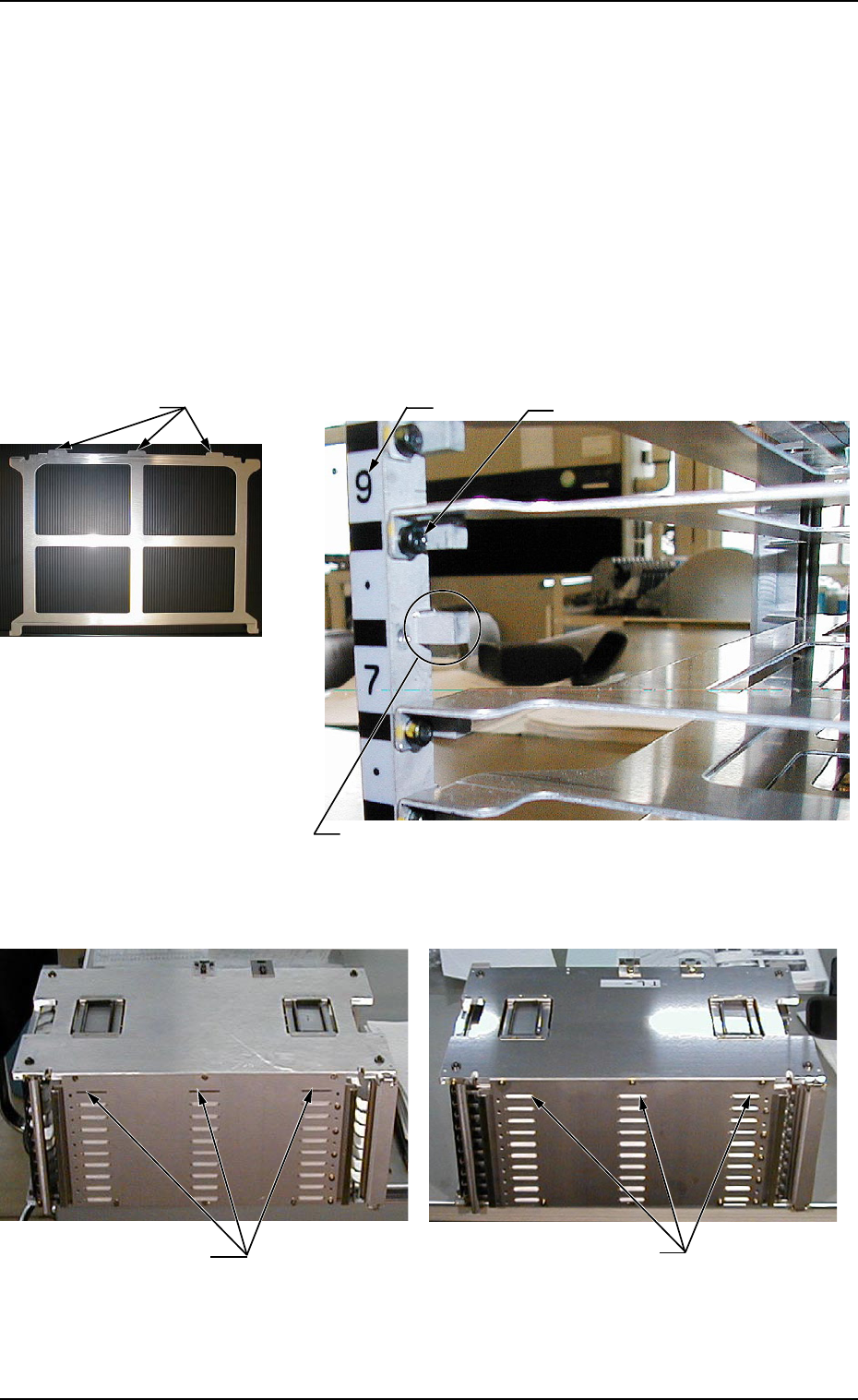
(3) Place the partition plate on the fixing block (refer to Fig. 1.25) and insert
it in the magazine so that the projections of the partition plate come out
from the openings at the rear wall of the magazine. (Refer to Figs. 1.26-
1 and 1.26-2).
Note : When the partition plate is being set in the magazine, note the direction
of the partition plate. Handle the magazine door and partition plate care-
fully because they are easily deformed. If the magazine door or parti-
tion plate is deformed, an error or machine breakdown might be caused.
Fig. 1.26-1
Fig. 1.26-2
Fig. 1.25 Fixing Block (On the Left) Positions
(Same for on the Right)
Fig. 1.24 Partition Plate
Bolt
Step No.
Fixed block with the partition plate removed
Opening where the partition
plate protrusions are inserted
Condition showing protrusions
coming out from the openings
Protrusions
0112-004 Chapter 1 2-20