OM-1068-001.pdf - 第86页
4. Set-up and Flow Chart for Automatic Operation • The shadowed items are related to the multi-layer tray feeders. Follow the procedures (outline) below before actually producing P .C.B.’ s for details. Refer to “5., 6.,…

3. Power Source Check and Power-Up Procedures
Refer to “3. Confirmation and Procedure of Power Supply of Section 2 in
Volume 1” in the main machine instruction manual for details.
• The tray feeders are not provided with any power breaker cranks and
[POWER ON] switches.
The power breaker crank and the [POWER ON] button of the main machine
are commonly used for the feeders.
• Power and air are supplied to the tray feeders from the main machine.
3. Power Source Check and Power-Up Procedures
0010-002 Chapter 1 2-6 Tg0252-PM-SO
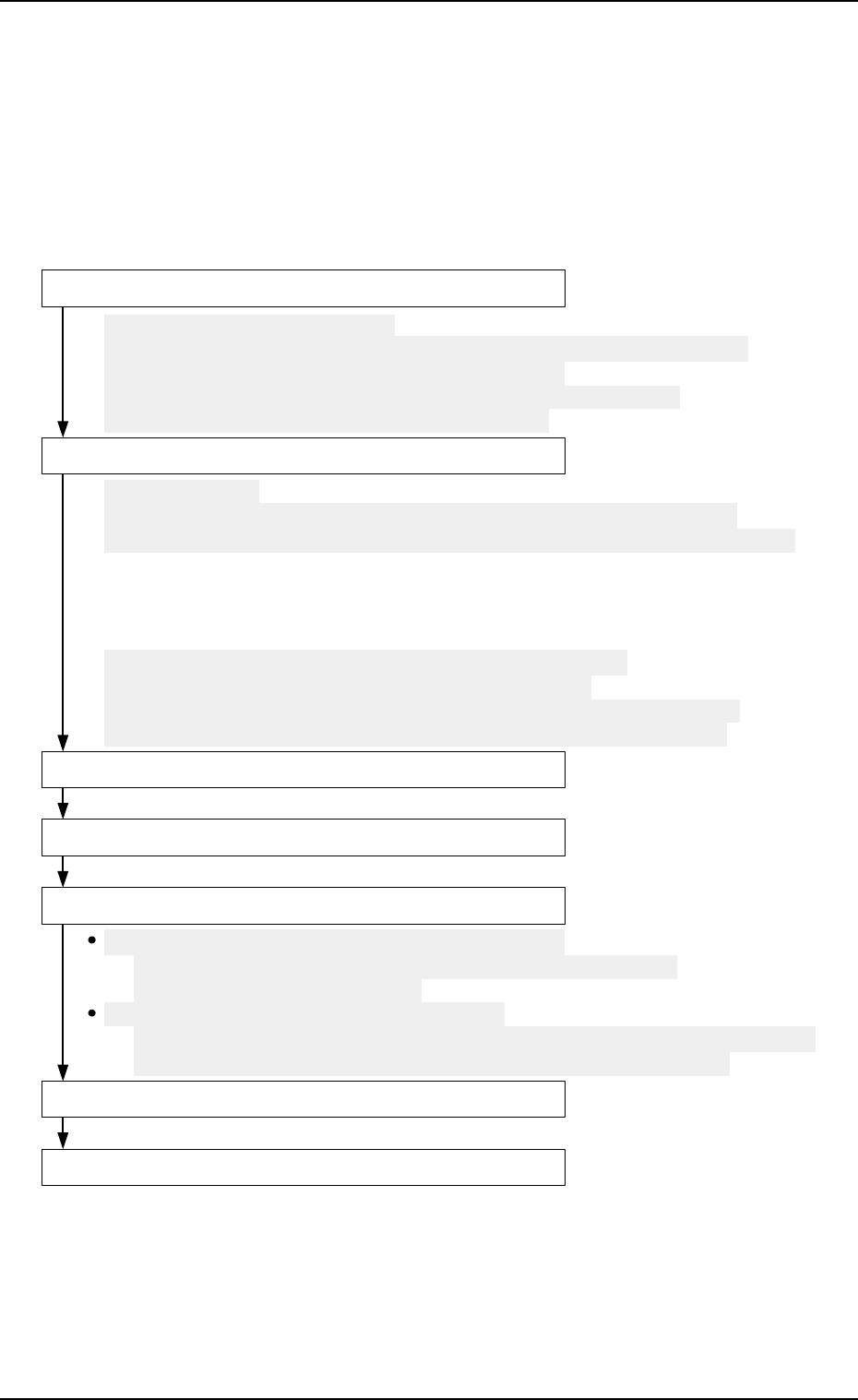
4. Set-up and Flow Chart for Automatic Operation
• The shadowed items are related to the multi-layer tray feeders.
Follow the procedures (outline) below before actually producing P.C.B.’s
for details.
Refer to “5., 6., and 10. of Section 2 in Chapter 1” for details.
4. Set-up and Flow Chart for Automatic Operation
0010-002 Chapter 1 2-7 Tg0252-PM-SO
Component Replenishment during Automatic Operation
Refer to "7.1 Component Supply During Automatic Operation of
Section 2 in Chapter 1" for details.
Possible Operations during Automatic Operation
Refer to "11.1.3 Tray Chuck Matrix Change Operations of Section 2 in Chapter 1"
and "4. Matrix Change Operations of Section 3 in Chapter 1" for details.
Preparation for Pattarn Program
Program Change Operation
Pattern Program Checking for Production Model
Setting of Operation Mode
Start of Automatic Operation
Stop of Automatic Operation
Shut-Down Operation
(1) Preparation for Component Library
Refer to "5.1.1 Component Library Data of Section 2 in Chapter 1" for details.
(2) Creation of Pattern Program Data for Production Model
Refer to "5.1.2 Component Data of Section 2 in Chapter 1" for details.
(3) Registration of Pattern Program for Production Model
(1) Zeroing Operation
Refer to"2. Zeroing Operation of Section 4 in Chapter 1" and "11.1.2 Zeroing
Operation Maneuvered on Main Machine Side of Section 2 in Chapter 1" for details.
(2) Selection of Current Pattern program (Program Change)
(3) Adjustment of P.C.B. Positioning Section
(4) Preparation for Nozzle Stocker Section
(5) Preparation for Multi-Layer Tray Feeder
Refer to "5.2.1 Preparation of Pallet of Section 2 in Chapter 1",
"5.2.2 Preparation of Magazine of Section 2 in Chapter 1",
"5.2.3 Attachment and Detachment of Magazine of Section 2 in Chapter 1",
"5.2.4 FEEDER (B) OFFSET Display of Section 2 in Chapter 1" for details.
5. Preparation and Confirmation before Operation
5.1 Preparation (Outline) for Pattern Program
5.1.1 Component Library Data
Editing Procedure of Component Library Data for FP-5021L
(The same procedure applies to the component library data for
FP-5021R.)
Refer to “COMPONENT LIBRARY” in main machine instruction manual for
details.
Data can be edited on the main machine side.
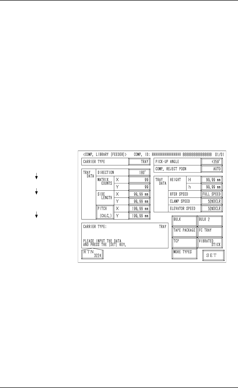
(1) When the [TRAY] key is pressed at the “COMP. LIBRARY [FEEDER]”
display, the following display appears on the screen.
(2) Enter the component library data.
Note: The component library data cannot be edited with the main ma-
chine in the “RUN” or “WAIT” mode when the multi-layer tray
feeder is included in the production model.
Fig. 1.10
Hierarchical Sequence
(Display)
“MAIN MENU”
“DATA EDIT”
“COMPONENT LIBRARY
EDIT”
“COMP. LIBRARY
[FEEDER]”
5. Preparation and Confirmation before Operation
0005-002 Chapter 1 2-8 Tg0252-PM-SO