OM-1068-001.pdf - 第82页
2. INITIALIZA TION Display When the main machine is powered up, power is also supplied to the multi- layer tray feeders. Then, the display (Fig. 1.6) appears on the touch screen of the multi-layer tray feeder . Fig. 1.6 …
1. Precautionary Items
1.1 Touch Screen
• The touch screen is constructed of a liquid crystal display (resolution: 320 ×
240 dots) and a touch screen.
The touch screen senses the placement of a user’s finger. To enter data or
select various data, press your finger slightly against the touch-sensitive
regions of the touch screen.
• The touch screen is made of glass.
Do not apply strong pressure to the touch screen. Try not to touch the screen
except for input operations.
The touch screen reacts to the force of 0.98 N (100 gf) or less.
Do not press the screen with an excessive force.
CAUTION
The surface of the touch screen is fragile. Do
not rub the surface not touch it with a pen, a
screwdriver, etc.
CAUTION
The device is not a water-proof and encapsu-
lated type.
Avoid dust, water droplet, oil droplet, and metal
pieces.
Especially, when metal pieces or combustible
material are mixed into the machine, it may
lead to fire ignition.
• A high-voltage current is flowing in some internal sections.
CAUTION
Do not detach nor disassemble the touch
screen to avoid any electric shock.
• Cleaning of Touch Screen
CAUTION
Turn off the operation power before the touch
screen is cleaned.
Cleaning the screen while it is active may cause
adverse reaction of the screen, resulting in data cor-
ruption.
When the surface of the touch screen is stained, wipe off dust and dirt with
a dry cloth.
If the surface still remains dirty, soak the cloth in diluted neutral detergent
(2%), wring it hard, then wipe off the dust and dirt.
CAUTION
Do not use alcohol or benzene to clean the
touch screen.
Otherwise, the surface of the touch screen may melt
or get cloudy.
1. Precautionary Items
9911-001 Chapter 1 2-2 Tg0252-PM-SO

2. INITIALIZATION Display
When the main machine is powered up, power is also supplied to the multi-
layer tray feeders.
Then, the display (Fig. 1.6) appears on the touch screen of the multi-layer tray
feeder.
Fig. 1.6 “INITIALIZATION” Display
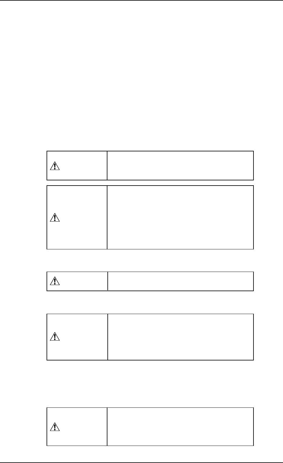
When the initialization is completed, the display (Fig. 1.7) appears on the
screen.
Shown in Fig. 1.7 is the condition called “Neutral Mode”.
When “LINE MODE” or “LOCAL MODE” is selected at this display, the
corresponding display appears on the screen.
[LINE MODE] Key : When this key is selected, the main machine issues a
command to set the feeder in the “LINE” mode.
Note: Automatic operation cannot be performed
unless the feeder is set in the “LINE” mode.
[LOCAL MODE] Key: Only the multi-layer tray feeder can be operated.
This mode is provided for performance check, etc.,
of the multi-layer tray feeder.
2. INITIALIZATION Display
9911-001 Chapter 1 2-3 Tg0252-PM-SO
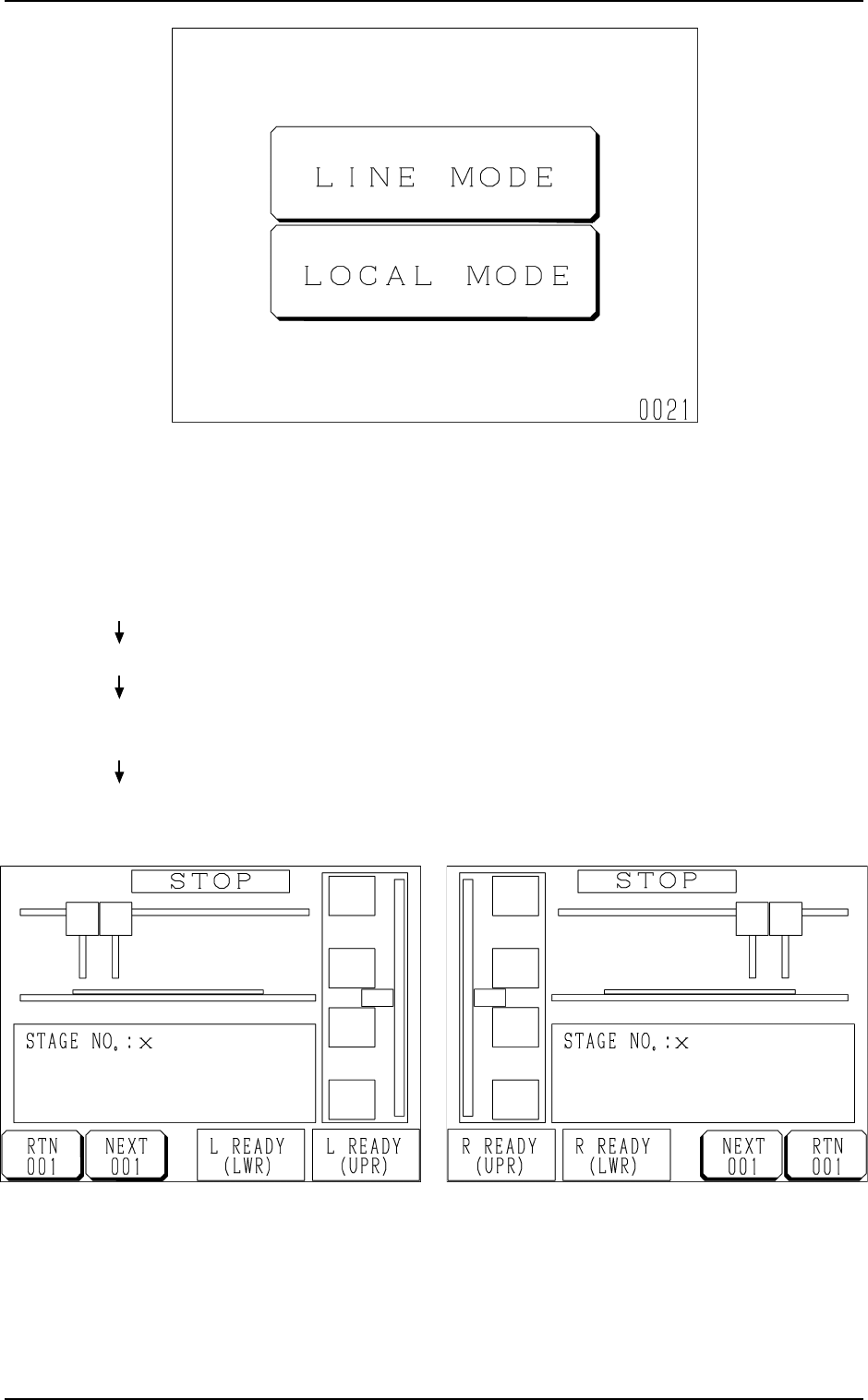
• When the [LINE MODE] key is pressed, the feeder is set in the
“LINE” mode and the display (Fig. 1.8-1 or 1.8-2) appears on
the screen.
Ref.: The “LINE” mode can also be set from the main ma-
chine side.
Refer to “11.1.1 Changing from “NEUTRAL” to “LINE”
Mode of Section 2 in Chapter 1” for details.
Fig. 1.8-2 FP-5021R
Fig. 1.8-1 FP-5021L
2. INITIALIZATION Display
Hierarchical Sequence
(Display)
“MAIN MENU”
“DATA EDIT”
“AUTO OPN MODE
(PLACEMENT)”
“AUTO OPN
SUB-MENU”
Fig. 1.7 Neutral Mode (Display for Mode Selection)
9911-001 Chapter 1 2-4 Tg0252-PM-SO