OM-1068-001.pdf - 第247页
Chapter 5 1-12 Tg0252-PM-SO Upper Magazine Clutch Connection (1) Forward Limit Upper Magazine Clutch Connection (1) Backward Limit Upper Magazine Clutch Connection (2) Forward Limit Upper Magazine Clutch Connection (2) B…
Chapter 5 1-11 Tg0252-PM-SO
From Main Machine
From Interlock Circuit
From Main Machine
2.3 Power Supply Circuit Diagram 1
2. Electrical Circuit Diagrams
LCD for Loaded Power Source
To Node
CH2-43
Notes :(a) It shows the diagram within dotted lines is within
the relay PCB.
(b) Note 1 shows the diagram without dotted lines is
within the relay PCB.
(c) For the diode in Note 2, DS446 is used.
To Operation
Monitor
From Main Machine
Note.1
Note.1
Note.1
Note2
Note.1
0010-003-(M742WTL--2102)
Chapter 5 1-12 Tg0252-PM-SO
Upper Magazine Clutch
Connection
(1) Forward Limit
Upper Magazine Clutch
Connection
(1) Backward Limit
Upper Magazine Clutch
Connection (2) Forward
Limit
Upper Magazine Clutch
Connection (2)
Backward Limit
Upper Magazine Normal
Position Check
Lower Magazine Clutch
Connection
(1) Forward Limit
Lower Magazine Clutch
Connection
(1) Backward Limit
Lower Magazine Clutch
Connection (2) Backward
Limit
Lower Magazine Normal
Position Check
Elevator Shaft Powered-
Up Indication Lamp
Upper Door Electro-
magnetic Lock
Lower Door Electro-
magnetic Lock
Lower Magazine Clutch
Connection (2) Backward
Limit
To K501
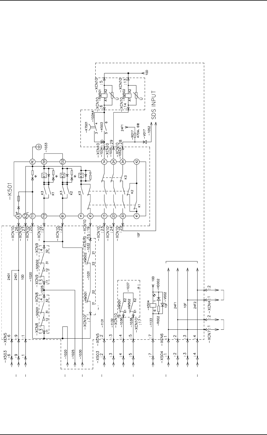
2.4 Power Supply Circuit Diagram 2
2. Electrical Circuit Diagrams
Note: It shows the diagram within dotted lines is within the relay PCB.
0010-002-(M742WTL--2103)
Chapter 5 1-13 Tg0252-PM-SO
Circuit Breaker OFF
Elevator Safety Relay ON
Servomotor Power-Up Check (1)
Servomotor Power-Up Check (2)
Upper Magazine Base Connection Check
Lower Magazine Base Connection Check
Upper Door Electromagnetic Switch
Lower Door Electromagnetic Switch
Pallet Stopper Cancellation
Pallet Direction Detection
Reserved
Start Switch (MOVE)
Stop Switch (STOP)
U READY Switch
(U READY)
L READY switch
(L READY)
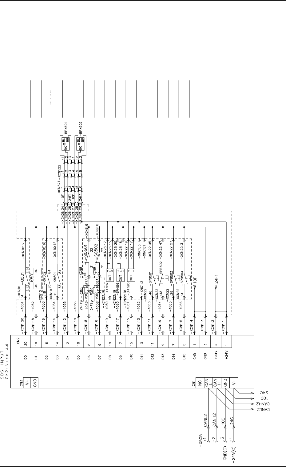
2.5 SDS IN 1
2. Electrical Circuit Diagrams
Cylinder Backward Limit
Notes : (a) It shows the diagram within dotted lines is within the relay PCB.
(b) Note 1 shows the diagram without dotted lines is within the relay
PCB.
(c) For the diode in Note 2, DS446 is used.
Resistances -R018 and -R019: 470Ω, 6W
Note.1
Note.2
Note.2
Note.1
0112-004 A(M742WTL--2104)