OM-1068-001.pdf - 第78页
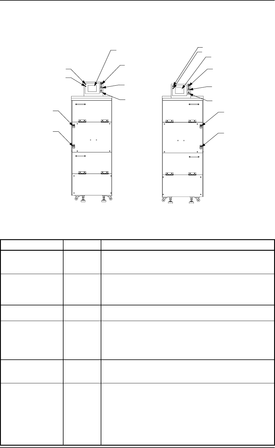
5. Operation Panel (Names and Functions) Name Symbols Function L READY -SPB504 (-HD504) • This bu tton sw itch is used to te ll the m ain m achine that the lower m agaz ine is set rea dy for r eplacem ent. • When the LED…
Power Supply for
Elevator
-HD502
[MOVE] Button
-SPB501 (-HD501)
[STOP] Button
-SPB502
POWER (LED)
RUN (LED)
5. Operation Panel (Names and Functions)
Table 1.1
Fig. 1.4
5. Operation Panel (Names and Functions)
[U READY] Button
-SPB503 (-HD503)
[L READY] Button
-SPB504 (-HD504)
POWER (LED)
RUN (LED)
Operation Monitor
(Touch Screen)
Power Supply for Elevator
-HD502
[MOVE] Button
-SPB501 (-HD501)
[U READY] Button
-SPB503 (-HD503)
[L READY] Button
-SPB504 (-HD504)
Name Symbols Function
Operation Monitor
(Touch Screen)
•
This touch screen displays various information about the
multi-layer tray feeders and the commands related to the
multi-layer tray feeder operation.
POWER
(LED)
•
This indicates whether or not power is supplied to the touch
screen.
•
When the LED is "ON", it indicates that power is supplied to
the touch screen.
RUN (LED)
•
When the LED is "ON", it indicates that the touch screen is
operational.
MOVE -SPB501
(-HD501)
•
This button switch is used to execute the manual control
functions labeled on the touch screen of the multi-layer tray
feeder.
•
When the LED is "ON", it indicates that the selected function
is being executed.
STOP -SPB502
•
This button switch is used to interrupt the execution of the
selected manual control function labeled on the touch screen
of the multi-layer tray feeder.
U READY -SPB503
(-HD503)
•
This button switch is used to tell the main machine that the
upper magazine is set ready for replacement.
•
When the LED is "ON", it indicates that the upper magazine
is already set ready for replacement.
•
When the LED flickers, it indicates that the upper magazine is
being shifted to the replacement mode.
•
When the LED is "OFF", it indicates that the upper magazine
is set ready for replacement.
FP-5021LFP-5021R
[STOP] Button
-SPB502
Operation Monitor
(Touch Screen)
9911-001 Chapter 1 1-10 Tg0252-PM-SO

5. Operation Panel (Names and Functions)
Name Symbols Function
L READY -SPB504
(-HD504)
•
This button switch is used to tell the main machine that the
lower magazine is set ready for replacement.
•
When the LED is "ON", it indicates that the lower magazine
is already set ready for replacement.
•
When the LED flickers, it indicates that the lower magazine is
being shifted to the replacement mode.
•
When the LED is "OFF", it indicates that the lower magazine
is set ready for replacement.
ELEV. POWER -HD502
•
This indicates whether or not power is supplied to the elevator
shaft.
•
When the LED is "ON", it indicates that power is supplied to
the elevator shaft.
9911-001 Chapter 1 1-11 Tg0252-PM-SO
6. Scope of Actions
(1) A tray (a pallet) is pulled out from the magazine stored in the elevator
section onto the traverses by the tray traverse of the main machine ac-
cording to the pattern program data.
(2) The placement heads of the main machine pick up components from the
tray pulled out onto the traverses.
(3) The images of the picked components (the components picked up by the
placement heads) are captured and recognized by the component cam-
eras to detect the deviation in the pick-up position. The detected devia-
tion is corrected and the components are placed accurately on the speci-
fied positions.
When a pick-up error or a recognition error is detected during the com-
ponent recognition, the machine performs the discharge operation of the
rejected component.
(4) The tray on the traverses is stored in the elevator and the subsequent tray
is pulled out onto the traverses according to the pattern program data.
When the subsequently placed component originates from the same tray,
the tray stays on the traverses.
(5) Steps (2) through (4) are repeated.
When the tray (specified in the pattern program data) becomes empty of
components, the error message “Material Shortage Error” appears on the
operation monitor.
In this case, press the [RTN] key to open the “COMPONENT REPLEN-
ISHMENT” display.
The related step No. flickers.
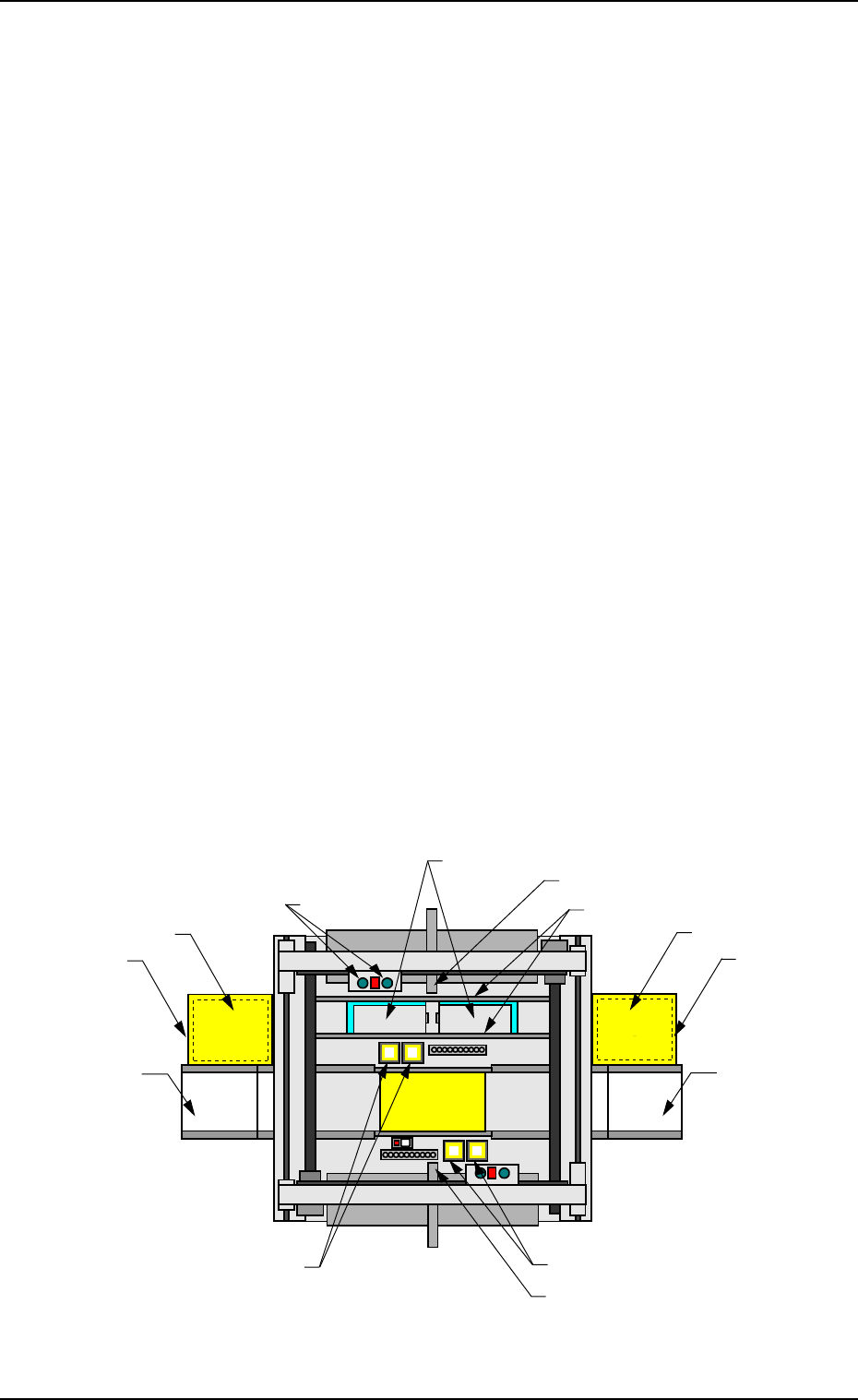
Beam A Side
Beam B Side
(Front Side of Machine)
Fig. 1.5 Appearance
6. Scope of Actions
P.C.B.
Multi-Layer Tray
Feeder
FP-5021R
ER Conveyor
(Option)
Component Storage Box
Elevator Section
EL Conveyor
(Option)
Multi-Layer Tray
Feeder
FP-5021L
Placement Head
Tray
(Pallet)
Traverses
Elevator Section
Component Recognition Camera
Component Recognition Camera
Component Storage Box
0005-002 Chapter 1 1-12
Tg0252-PM-SO