OM-1068-001.pdf - 第165页
0005-002 Chapter 3 2-4 Tg0252-PM-SO 3. Error Messages 3. Error Messages Main Section Error Messages ( *A ) 1 1H T ravers e 1 01H 02H 03H 04H 05H 06H TV1-AXIS ORIGIN TV1-AXIS TIMING TV1-AXIS DA T A TV1-AXIS LI MIT TV1-AXI…

0005-002 Chapter 3 2-3 Tg0252-PM-SO
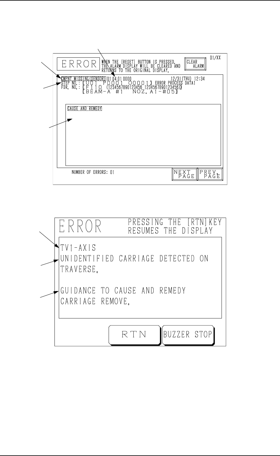
A : Error Message
B : Details of Error Message
C : Guidance to the Cause and Remedy of Error
(Some errors may not be displayed.)
Refer to “4. Troubleshooting after Error Messages of Section 2 in Chapter 3”
for details (error messages, details of error messages, cause, remedy, etc.).
D : This key is used to stop buzzer sound.
E : Buzzer sound stops and the display before an error has occurred resumes.
2. Remedial Procedure after Error Display
Operation Procedure
(1) Press the [BUZZER STOP] key.
(See Fig. 3.2.)
The buzzer stops sounding.
(2) Check the contents of the error message and the remedial procedure
(GUIDANCE TO CAUSE AND REMEDY) displayed on the operation
monitor.
Ref.: “4. Troubleshooting after Error Messages of Section 2 in Chapter
3” for details.
(3) Remove the cause of the error.
Different countermeasures and remedial procedures must be taken,
depending on the type of an error.
• Remedial Procedure when power must be re-supplied or the system
clear operation must be performed
(1) Refer to “6.7.2 Reset and Start Procedure from Emergency Stop
of Section 2 in Volume 1” in the main machine instruction
manual for details.
• Remedial Procedure when the zeroing operation must be performed
(1) Press the [RTN] key.
(2) Perform the zeroing operation.
Refer to “2. Zeroing Operation of Section 4 in Chapter 1” for
details.
• Remedial Procedure when the cause of an error is removed without
performing the zeroing or the system clear operation or just for
message confirmation
(1) Press the [RTN] key.
(2) The display before the “ERROR” display resumes.
(3) Refer to the instructions (GUIDANCE TO CAUSE AND
REMEDY) and remove the cause.
2. Remedial Procedure after Error Display
0005-002 Chapter 3 2-4 Tg0252-PM-SO
3. Error Messages
3. Error Messages
Main Section Error Messages (
*A
)
11H Traverse 1 01H
02H
03H
04H
05H
06H
TV1-AXIS ORIGIN
TV1-AXIS TIMING
TV1-AXIS DATA
TV1-AXIS LIMIT
TV1-AXIS INTERLOCK
POWER ON MONITOR
12H Traverse 2 01H
02H
03H
04H
05H
06H
TV2-AXIS ORIGIN
TV2-AXIS TIMING
TV2-AXIS DATA
TV2-AXIS LIMIT
TV2-AXIS INTERLOCK
POWER ON MONITOR
13H Elevator 1 01H
02H
03H
04H
05H
06H
07H
08H
EV1-AXIS ORIGIN
EV1-AXIS TIMING
EV1-AXIS DATA
EV1-AXIS LIMIT
EV1-AXIS SERVO
EV1-AXIS INTERLOCK
MAGAZINE CONNECTION
POWER ON MONITOR
14H Elevator 2 01H
02H
03H
04H
05H
06H
07H
08H
EV2-AXIS ORIGIN
EV2-AXIS TIMING
EV2-AXIS DATA
EV2-AXIS LIMIT
EV2-AXIS SERVO
EV2-AXIS INTERLOCK
MAGAZINE CONNECTION
POWER ON MONITOR
6FH Multi-Layer Tray
Feeder (L)
01H SHORTAGE OF COMPONENT
FOR TRAY-L
70H Multi-Layer Tray
Feeder (R)
01H SHORTAGE OF COMPONENT
FOR TRAY-R
0005-001 Chapter 3 2-5 Tg0252-PM-SO
4. Troubleshooting after Error Message
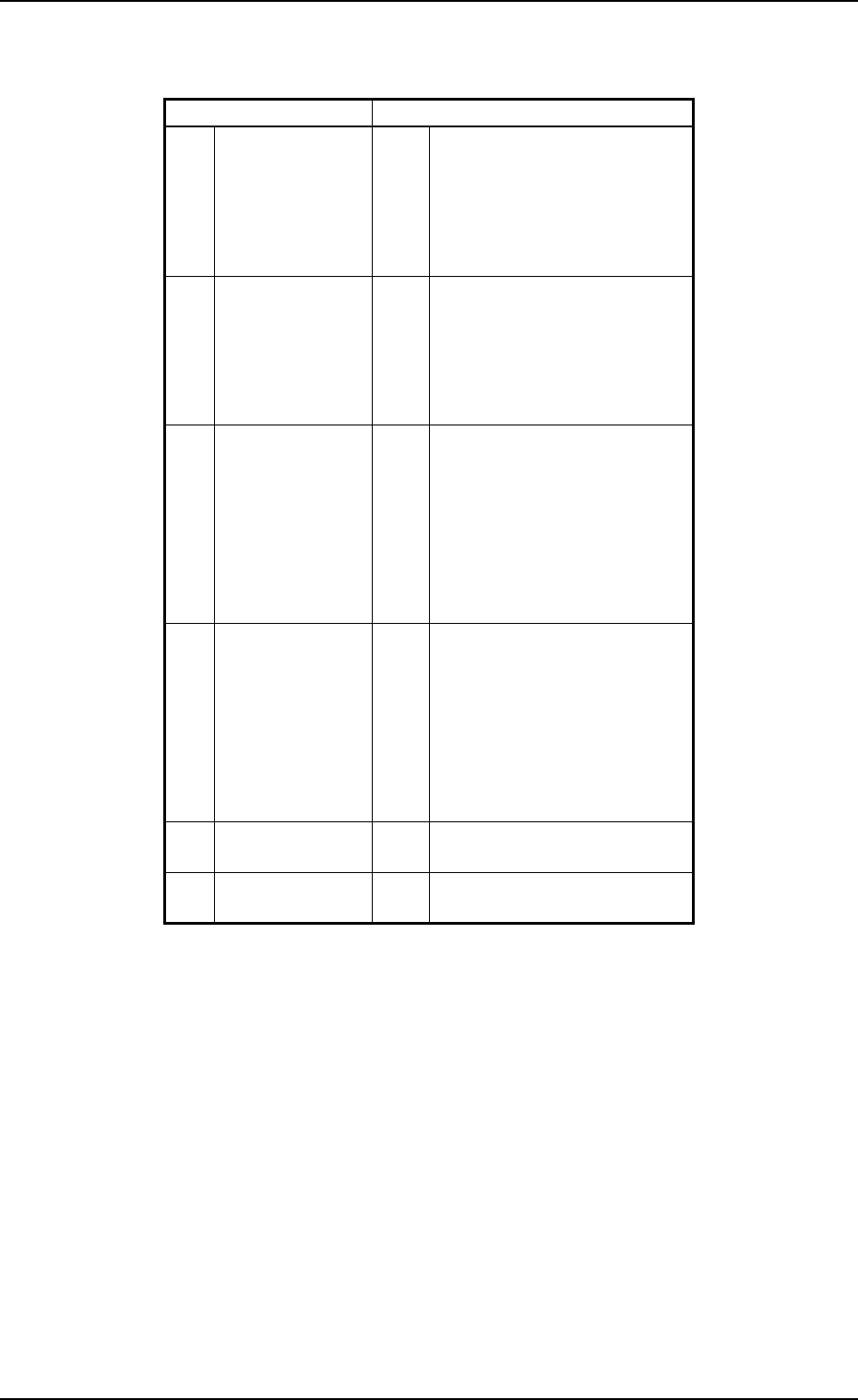
ERROR Display for the Main Body
ERROR Display for the Multi-Layer Tray Feeder
[ ERROR Indication Examples ]
Section A: Shows an ERROR message.
Section B: Shows the ERROR description.
Section C: Shows the Cause and Remedy Guide for the Error.
Section D: Indicates an ERROR code consisting of 6 digits.
4. Troubleshooting after Error Message
Fig. 3.3
D
Fig. 3.4
C
B
A
B
A
C