OM-1068-001.pdf - 第184页
01 12-001 C h ap t er 3 2-23 Tg0252-PM-SO 4. Troubleshooting after Error Message 12 02 0 1 TV2-AXIS TIMING PREVIOUS T ASK W AS NOT COMPLETED. UNABLE T O CONTINUE. 12 0 3 01 TV2-AXIS DA T A T ARGET LOCA TION V ALUE IS OUT…
0112-001 Chapter 3 2-22 Tg0252-PM-SO
4. Troubleshooting after Error Message
12 01 0A TV2-AXIS ORIGIN TRAVERSE AXIS (+) LIMIT [BPH256] SENSOR MAY BE
DEFECTIVE.
12 01 0B TV2-AXIS ORIGIN TRAVERSE 2 LEVER A ORIGIN [BPH264] NOT DE-
TECTED.
Error Code Display A Display B
(Cause 1) This is the device’s self-diagnostic message.
(Reset Procedure in the case of Cause 1)
Reset Procedure
(1) Press the [CLEAR ALARM] key to stop the buzzer sound.
(2) Press the [RESET] button to cancel the error mode.
(3) Press the [ZERO] button to return all axes to their original positions. Continue the production
according to the “WARM Start Operation Procedure”.
(4) If the device can’t be reset after the above procedure, contact our service personnel.
12 01 0C TV2-AXIS ORIGIN TRAVERSE 2 LEVER B ORIGIN [BPH265] NOT DE-
TECTED.
(Cause 1) This is the device’s self-diagnostic message.
(Reset Procedure in the case of Cause 1)
Reset Procedure
(1) Press the [CLEAR ALARM] key to stop the buzzer sound.
(2) Press the [RESET] button to cancel the error mode.
(3) Press the [ZERO] button to return all axes to their original positions. Continue the production
according to the “WARM Start Operation Procedure”.
(4) If the device can’t be reset after the above procedure, contact our service personnel.
12 01 0D TV2-AXIS ORIGIN TRAVERSE 2 CLAMP AREA CHECK A [BPH264] NOT
DETECTED.
12 01 0E TV2-AXIS ORIGIN TRAVERSE 2 CLAMP AREA CHECK B [BPH254] NOT
DETECTED.
(Cause 1) This is the device’s self-diagnostic message.
(Reset Procedure in the case of Cause 1)
Reset Procedure
(1) Press the [CLEAR ALARM] key to stop the buzzer sound.
(2) Press the [RESET] button to cancel the error mode.
(3) Press the [ZERO] button to return all axes to their original positions. Continue the production
according to the “WARM Start Operation Procedure”.
(4) If the device can’t be reset after the above procedure, contact our service personnel.
0112-001 Chapter 3 2-23 Tg0252-PM-SO
4. Troubleshooting after Error Message
12 02 01 TV2-AXIS TIMING PREVIOUS TASK WAS NOT COMPLETED. UNABLE TO
CONTINUE.
12 03 01 TV2-AXIS DATA TARGET LOCATION VALUE IS OUT OF RANGE.
Error Code Display A Display B
(Cause 1) This is the device’s self-diagnostic message.
(Reset Procedure in the case of Cause 1)
Reset Procedure
(1) Press the [CLEAR ALARM] key to stop the buzzer sound.
(2) Press the [RESET] button to cancel the error mode.
(3) Press the [ZERO] button to return all axes to their original positions. Continue the production
according to the “WARM Start Operation Procedure”.
(4) If the device can’t be reset after the above procedure, contact our service personnel.
12 04 01 TV2-AXIS LIMIT LIMIT ERROR (+) IS DETECTED.;BPH256
12 04 02 TV2-AXIS LIMIT LIMIT ERROR (-) IS DETECTED.;BPH257
(Cause 1) It may run away due to noise or overcurrent.
(Cause 2) The sensor may be defective.
(Reset Procedure in the case of Causes 1 and 2)
Reset Procedure
(1) Press the [CLEAR ALARM] key and the buzzer stops sounding.
(2) Press the [ZERO] button to return all the axes to their original positions.
(3) Re-start.
(4) If the device can’t be re-started, contact our service personnel.
0112-001 Chapter 3 2-24 Tg0252-PM-SO
4. Troubleshooting after Error Message
12 05 TV2-AXIS INTERLOCK Reserved
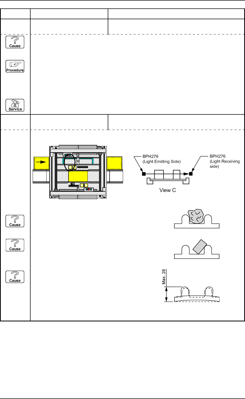
12 05 02 TV2-AXIS INTERLOCK TRAVERSE 1 PATH LINE [BPH276] DETECTED.
Error Code Display A Display B
(Cause 1) This is the device’s self-diagnostic message.
(Reset Procedure in the case of Cause 1)
Reset Procedure
(1) Press the [CLEAR ALARM] key to stop the buzzer sound.
(2) Press the [RESET] button to cancel the error mode.
(3) Press the [ZERO] button to return all axes to their original positions. Continue the production
according to the “WARM Start Operation Procedure”.
(4) If the device can’t be reset after the above procedure, contact our service personnel.
PCB
Beam A Side
Beam B Side
C
(Cause 1) Is there any foreign substance on the tray?
Check the tall component on the pallet.
(Cause 2) Is the component not properly in the tray?
A component which was not picked up might be
sticking out from the tray.
(Cause 3) Is the height of the tray close to the specified
maximum limit?
(NEXT PAGE)