OM-1068-001.pdf - 第238页
Tg0252-PM-SO 2. Electrical Circuit Diagrams 2. 1 Electrical Circuit Diagrams (Electrical and Electronic Symbols) “*” represents a numeral. 0005-002 C h ap t er 5 1 - 3 2. Electrical Circuit Diagrams
Tg0252-PM-SO
9911-001-(M676XTL--1101) Chapter 5 1-2
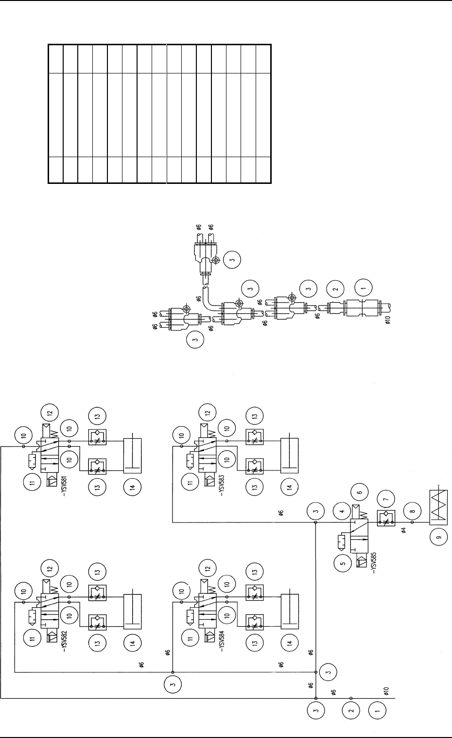
1. Air Piping Diagram (FP-5021L)
Upper Magazine (2)
Clutch Connection Cylinder
Lower Magazine
(2)
Clutch Connection
Cylinder
Upper Magazine (1)
Clutch Connection Cylinder
Lower Magazine (1)
Clutch Connection
Cylinder
To Upper Magazine (2)
Clutch Connection
To Lower Magazine (2)
Clutch Connection
Pallet Stopper
OFF
To Lower Magazine (1)
Clutch Connection
From TIM-5100
main machine
Details of Joint Connection
Pallet Stopper OFF Cylinder
To Upper Magazine (1)
Clutch Connection
From TIM-5100 main machine
1. Air Piping Diagram (FP-5021L)
No. Name Q t
y
1 Straight Union 1
2 Reducer 1
3 Union Y 4
4Half Union 1
5 Silencer 1
6 Solenoid Valve 1
7 Speed Controller 1
8 Elbow 1
9 Air Cylinder 1
10 Half Union 8
11 Silencer 4
12 Solenoid Valve 4
13 Speed Controller 8
14 Air Cylinder 4
Tg0252-PM-SO
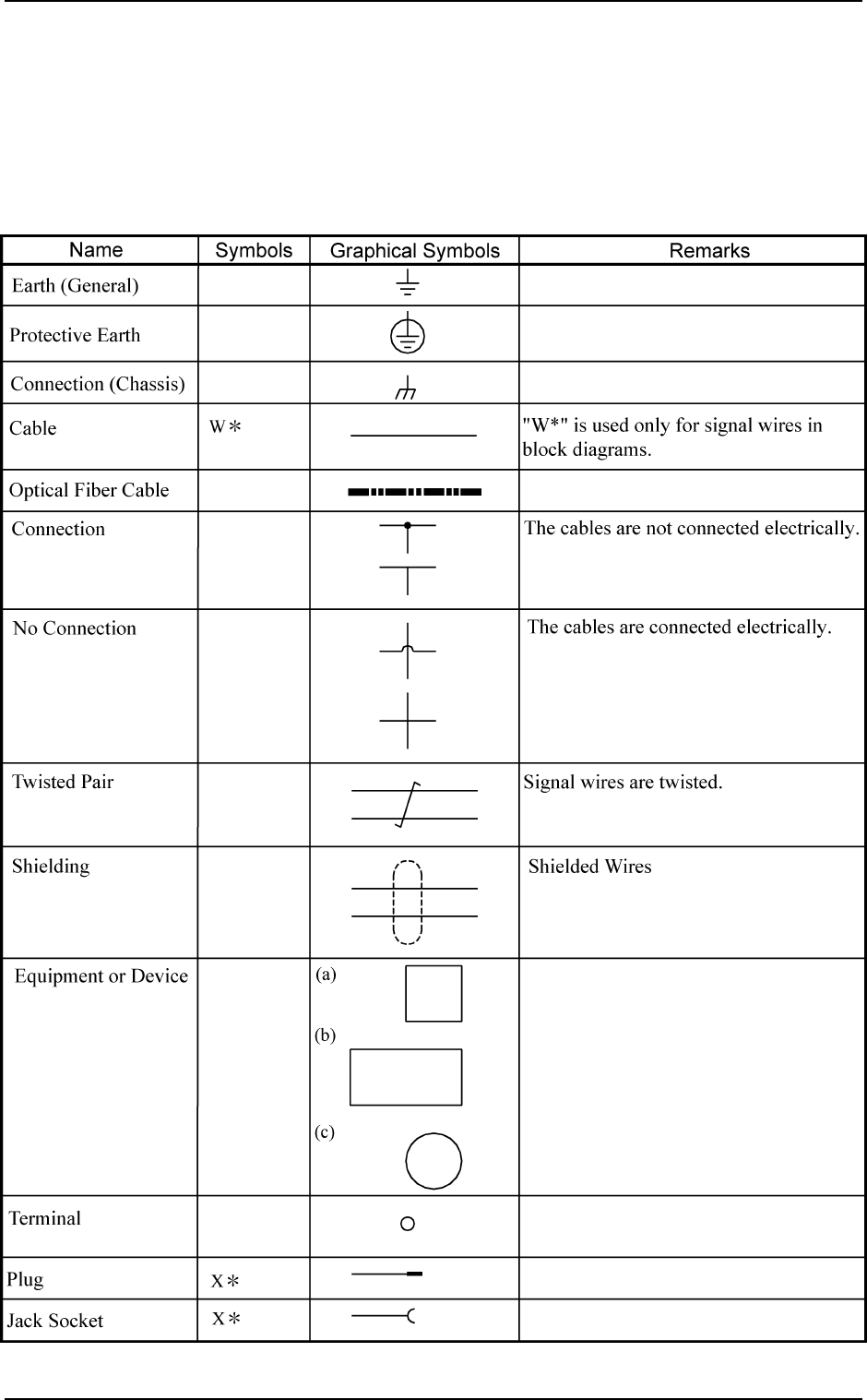
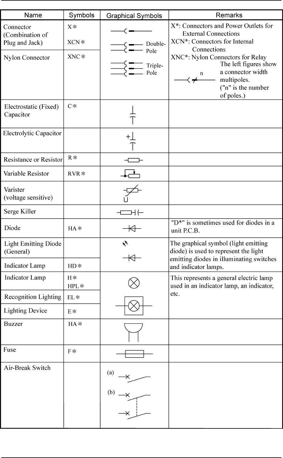
2. Electrical Circuit Diagrams
2.1 Electrical Circuit Diagrams (Electrical and
Electronic Symbols)
“*” represents a numeral.
0005-002 Chapter 5 1-3
2. Electrical Circuit Diagrams
Tg0252-PM-SO
9911-001 Chapter 5 1-4
2. Electrical Circuit Diagrams