OM-1068-001.pdf - 第114页
7. Component Replenishment during Automatic Operation The display of Fig. 1.39-1 or Fig. 1.39-2 on the screen calls for component replenishment. Fig. 1.40 7.1 Component Replenishment in “Component Shortage” Mode (1) When…

6.2 Temporary Stop Procedure
Press the “PAUSE” button on the main machine.
After the machine runs in its minimum cycle (single operating unit), it stops
running.
Note: “PAUSE” mode does not mean that the machine is completely stopped.
Take ample care when the machine is set in the “PAUSE” mode.
The machine starts running all of a sudden right after it receives a start
signal (a start signal is sent out when the [START] or the [MOVE]
button is pressed).
6.3 Start Procedure from “PAUSE” Mode
Press the [START] or the [MOVE] button on the main machine while the
“AUTO OPN. MODE <PLACEMENT>” display is active on the main ma-
chine side.
• When the [START] button is pressed, the machine starts automatic opera-
tion (“PLACE” Mode) from the step No. which is displayed on the screen of
the main machine.
When the automatic operation (component placement) starts, all origin marks
“” disappear and the LED (-HD01) of the [START] button and the tower
light (green) illuminates.
• When the [MOVE] button is pressed, the machine places the components
related to the step Nos. on the screen of the main machine and is set again in
the “PAUSE” mode.
Every time the [MOVE] button is pressed, the machine places components
one by one in the order of step Nos.
While the machine is activated, the LED (-HD02) of the [MOVE] button
illuminates.
6. Start Procedure of Automatic Operation
0010-002 Chapter 1 2-30 Tg0252-PM-SO
7. Component Replenishment during Automatic
Operation
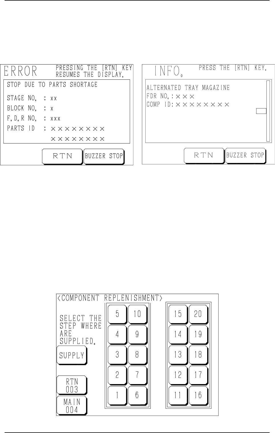
The display of Fig. 1.39-1 or Fig. 1.39-2 on the screen calls for component
replenishment.
Fig. 1.40
7.1 Component Replenishment in “Component Shortage”
Mode
(1) When a component shortage error occurs or the magazine alternate func-
tion is activated, the magazine in short of components moves to the set-
up position and is separated from the elevator shaft.
In this case, the “ERROR” display (Fig. 1.39-1) or the “INFO.” display
(Fig. 1.39-2) appears on the operation monitor.
Check the contents of the described items.
(2) Press the [BUZZER STOP] key.
The buzzer stops.
(3) Press the [RTN] key. The display (Fig. 1.40) appears on the screen.
7. Component Replenishment during Automatic Operation
Fig. 1.39-1 Fig. 1.39-2
9911-001 Chapter 1 2-31 Tg0252-PM-SO
(4) Check the stage (pallet) and the block which caused a component short-
age error.
When a block is specified, press the No. key of the stage where a com-
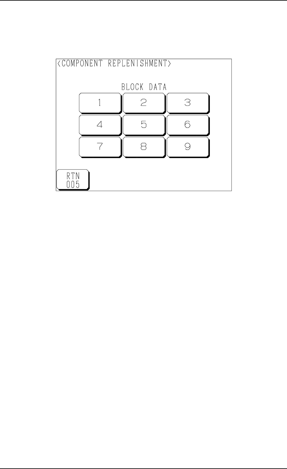
ponent shortage error has occurred. The display (Fig. 1.41) appears on
the screen, enabling you to check the block data.
Fig. 1.41
(5) Open the upper or the lower door and then the magazine door.
(6) Pull out the pallet on the stage in short of components and load it with
components.
When several stages and blocks are short of components, load all pallets
with components.
(7) Press the No. key of the stage in red (ON or flickering) at the display
(Fig. 1.40) and the No. key of the block in red (ON or flickering) at the
display (Fig. 1.41).
The keys turn violet.
(8) Confirm that all components are supplied completely and close all doors
(magazine, upper and lower doors).
7. Component Replenishment during Automatic Operation
9911-001 Chapter 1 2-32 Tg0252-PM-SO