OM-1068-001.pdf - 第261页
Chapter 5 2-4 Tg0252-PM-SO 2.2 Power Supply Circuit Diagram 1 2. Electrical Circuit Diagrams From Main Machine From Interlock Circuit From Main Machine LCD for Loaded Power Source T o Node CH2-43 Notes : ( a ) It shows t…
Chapter 5 2-3 Tg0252-PM-SO
2. Electrical Circuit Diagrams
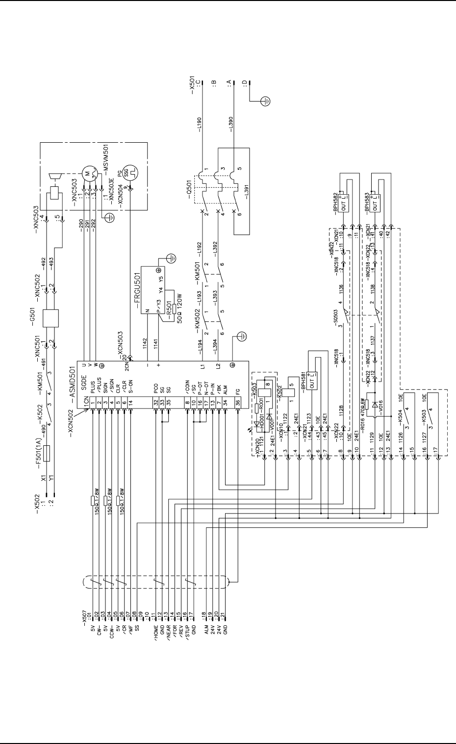
2.1 Elevator Circuit Diagram
2. Electrical Circuit Diagrams
Notes : (a) It shows the diagram within the dotted
lines is within the relay PCB.
(b) Use a pad of DS446 for the diode.
(c) For the diode DS446 is used.
Alarm
Brake
Elevator Shaft Origin
Elevator Shaft Overrun (+)
Elevator Shaft Limit (-)
Elevator Shaft
Encoder
Brake Power
Source
Brake
Emergency Stop
Alarm for Elevator Shaft
Note.b
0112-004 A(M742WTL--2101)
Chapter 5 2-4 Tg0252-PM-SO
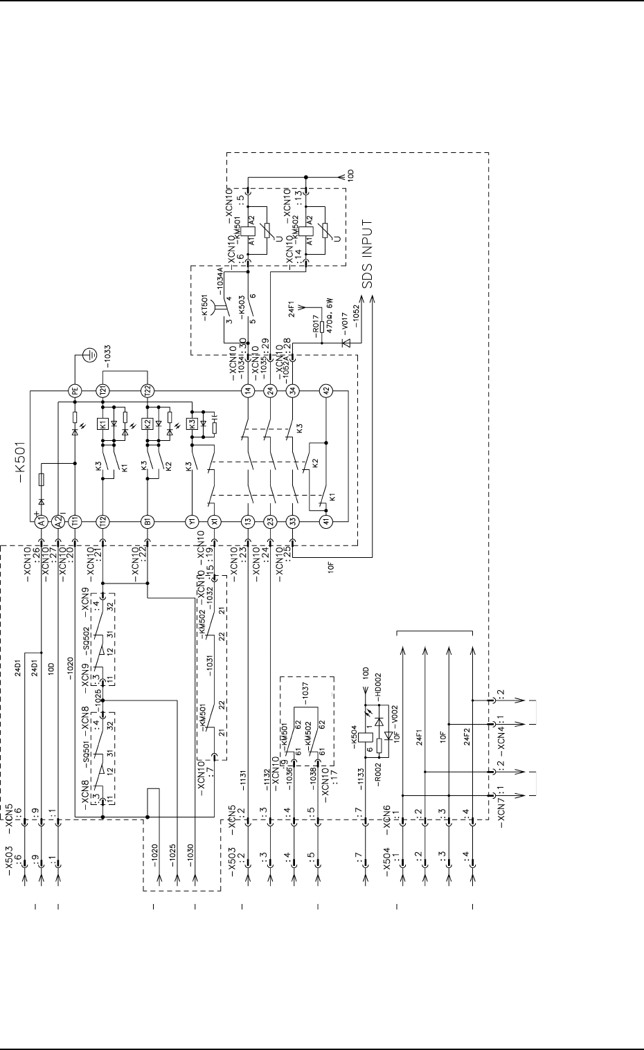
2.2 Power Supply Circuit Diagram 1
2. Electrical Circuit Diagrams
From Main Machine
From Interlock Circuit
From Main Machine
LCD for Loaded Power Source
To Node
CH2-43
Notes :(a) It shows the diagram within dotted lines is within
the relay PCB.
(b) Note 1 shows the diagram without dotted lines is
within the relay PCB.
(c) For the diode in Note 2, DS446 is used.
To Operation
Monitor
From Main Machine
Note.1
Note.1
Note.1
Note2
Note.1
0010-003-(M742WTL--2102)
Chapter 5 2-5 Tg0252-PM-SO
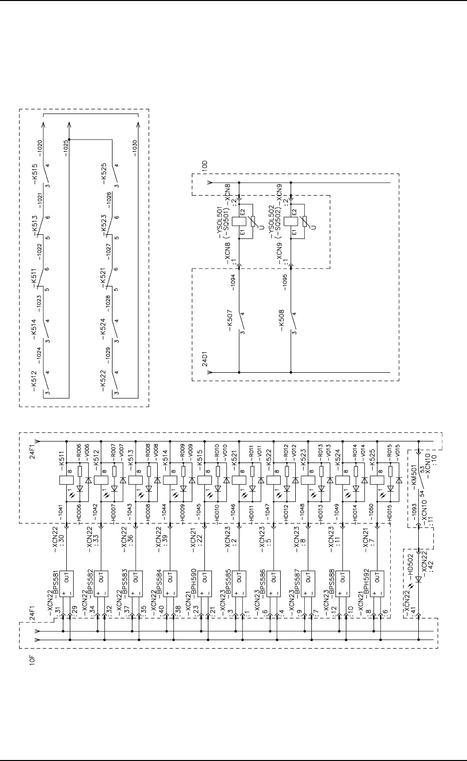
2.3 Power Supply Circuit Diagram 2
2. Electrical Circuit Diagrams
Upper Magazine Clutch
Connection
(1) Forward Limit
Upper Magazine Clutch
Connection
(1) Backward Limit
Upper Magazine Clutch
Connection (2) Forward
Limit
Upper Magazine Clutch
Connection (2)
Backward Limit
Upper Magazine Normal
Position Check
Lower Magazine Clutch
Connection
(1) Forward Limit
Lower Magazine Clutch
Connection
(1) Backward Limit
Lower Magazine Clutch
Connection (2) Backward
Limit
Lower Magazine Normal
Position Check
Elevator Shaft Powered-
Up Indication Lamp
Upper Door Electro-
magnetic Lock
Lower Door Electro-
magnetic Lock
Lower Magazine Clutch
Connection (2) Backward
Limit
To K501
Note: It shows the diagram within dotted lines is within the relay PCB.
0010-002-(M742WTL--2103)