OM-1068-001.pdf - 第84页
Fig. 1.9 • When the [LOCAL MODE] key is pressed, the following “LOCAL MODE” display appears on the screen, enabling the zeroing and manual operations of the multi-layer tray feeder . 2. INITIALIZA TION Display 991 1-001 …
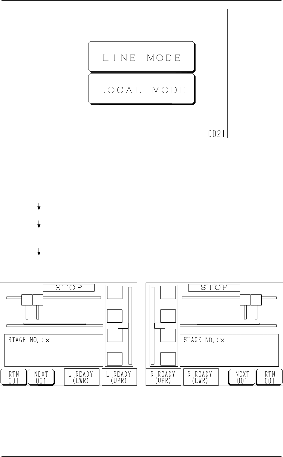
• When the [LINE MODE] key is pressed, the feeder is set in the
“LINE” mode and the display (Fig. 1.8-1 or 1.8-2) appears on
the screen.
Ref.: The “LINE” mode can also be set from the main ma-
chine side.
Refer to “11.1.1 Changing from “NEUTRAL” to “LINE”
Mode of Section 2 in Chapter 1” for details.
Fig. 1.8-2 FP-5021R
Fig. 1.8-1 FP-5021L
2. INITIALIZATION Display
Hierarchical Sequence
(Display)
“MAIN MENU”
“DATA EDIT”
“AUTO OPN MODE
(PLACEMENT)”
“AUTO OPN
SUB-MENU”
Fig. 1.7 Neutral Mode (Display for Mode Selection)
9911-001 Chapter 1 2-4 Tg0252-PM-SO
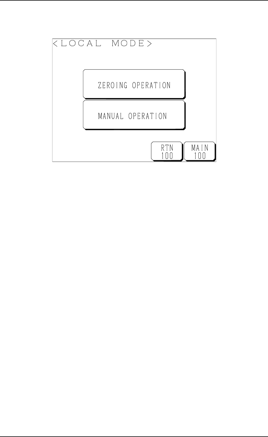
Fig. 1.9
• When the [LOCAL MODE] key is pressed, the following “LOCAL MODE”
display appears on the screen, enabling the zeroing and manual operations
of the multi-layer tray feeder.
2. INITIALIZATION Display
9911-001 Chapter 1 2-5 Tg0252-PM-SO

3. Power Source Check and Power-Up Procedures
Refer to “3. Confirmation and Procedure of Power Supply of Section 2 in
Volume 1” in the main machine instruction manual for details.
• The tray feeders are not provided with any power breaker cranks and
[POWER ON] switches.
The power breaker crank and the [POWER ON] button of the main machine
are commonly used for the feeders.
• Power and air are supplied to the tray feeders from the main machine.
3. Power Source Check and Power-Up Procedures
0010-002 Chapter 1 2-6 Tg0252-PM-SO