OM-1068-001.pdf - 第166页
0005-001 Chapter 3 2-5 Tg0252-PM-SO 4. T roubleshooting after Error Message ERROR Display for the Main Body ERROR Display for the Multi-Layer T ray Feeder [ ERROR Indication Examples ] Section A: Shows an ERROR message. …

0005-002 Chapter 3 2-4 Tg0252-PM-SO
3. Error Messages
3. Error Messages
Main Section Error Messages (
*A
)
11H Traverse 1 01H
02H
03H
04H
05H
06H
TV1-AXIS ORIGIN
TV1-AXIS TIMING
TV1-AXIS DATA
TV1-AXIS LIMIT
TV1-AXIS INTERLOCK
POWER ON MONITOR
12H Traverse 2 01H
02H
03H
04H
05H
06H
TV2-AXIS ORIGIN
TV2-AXIS TIMING
TV2-AXIS DATA
TV2-AXIS LIMIT
TV2-AXIS INTERLOCK
POWER ON MONITOR
13H Elevator 1 01H
02H
03H
04H
05H
06H
07H
08H
EV1-AXIS ORIGIN
EV1-AXIS TIMING
EV1-AXIS DATA
EV1-AXIS LIMIT
EV1-AXIS SERVO
EV1-AXIS INTERLOCK
MAGAZINE CONNECTION
POWER ON MONITOR
14H Elevator 2 01H
02H
03H
04H
05H
06H
07H
08H
EV2-AXIS ORIGIN
EV2-AXIS TIMING
EV2-AXIS DATA
EV2-AXIS LIMIT
EV2-AXIS SERVO
EV2-AXIS INTERLOCK
MAGAZINE CONNECTION
POWER ON MONITOR
6FH Multi-Layer Tray
Feeder (L)
01H SHORTAGE OF COMPONENT
FOR TRAY-L
70H Multi-Layer Tray
Feeder (R)
01H SHORTAGE OF COMPONENT
FOR TRAY-R
0005-001 Chapter 3 2-5 Tg0252-PM-SO
4. Troubleshooting after Error Message
ERROR Display for the Main Body
ERROR Display for the Multi-Layer Tray Feeder
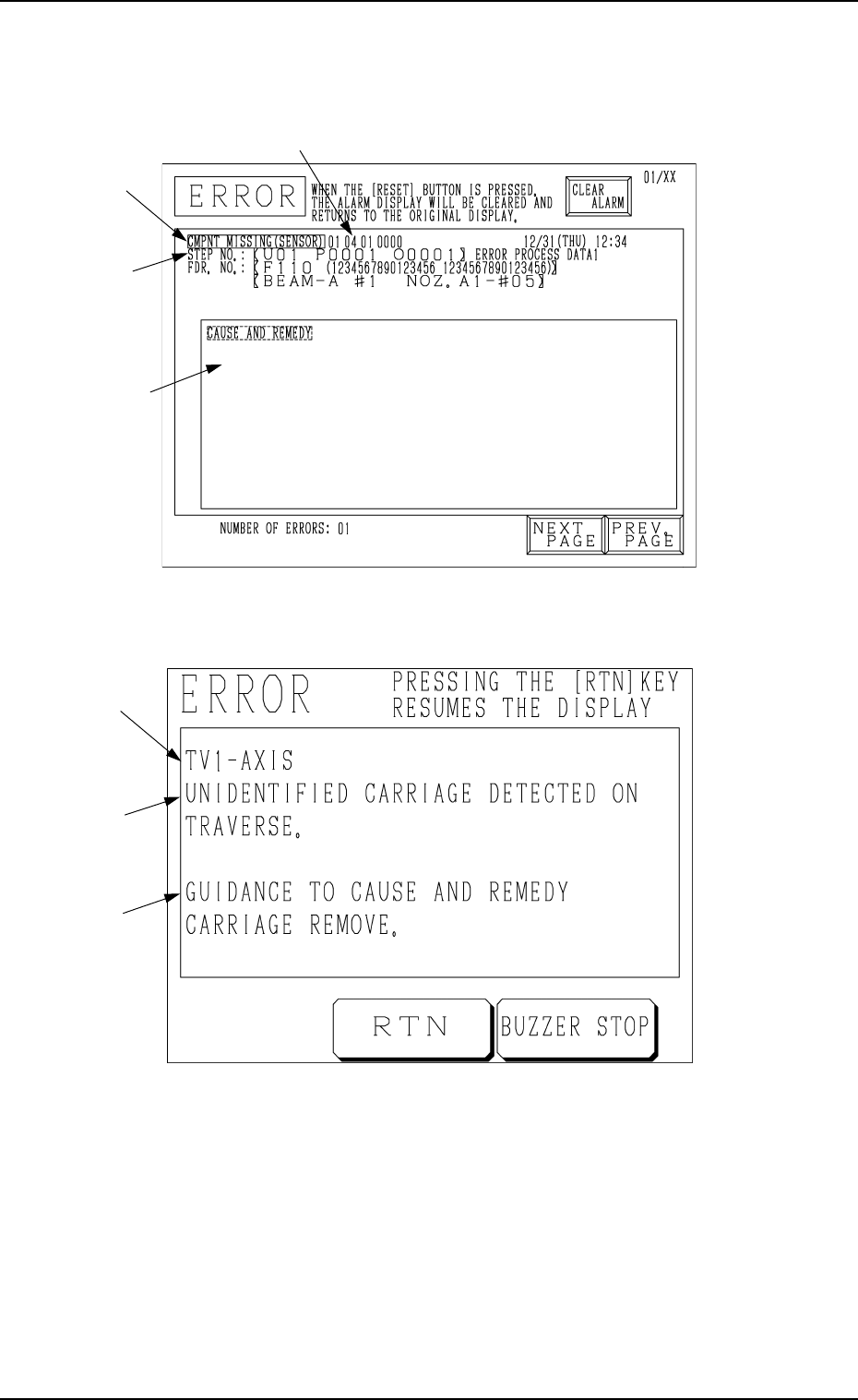
[ ERROR Indication Examples ]
Section A: Shows an ERROR message.
Section B: Shows the ERROR description.
Section C: Shows the Cause and Remedy Guide for the Error.
Section D: Indicates an ERROR code consisting of 6 digits.
4. Troubleshooting after Error Message
Fig. 3.3
D
Fig. 3.4
C
B
A
B
A
C
0112-003 Chapter 3 2-6 Tg0252-PM-SO
4. Troubleshooting after Error Message
Check “Section D Indication” (error code), “Section A Indication”, “Section B
Indication” and “Section C Indication” at the ERROR display: remedy the
device by referring to the following trouble shooting guide.
(Cause 1) Motor encoder section may be defective.
(Cause 2) Encoder cable may be broken.
(Reset Procedure in the case of Causes 1 and 2)
Reset Procedure
(1) Turn off the power and check for loose connections between the sections of the motor and
signal cable.
(2) Re-start.
(3) If the device can’t be reset even after the above check, contact our service personnel because
the signal cable may be broken or the motor may be defective.
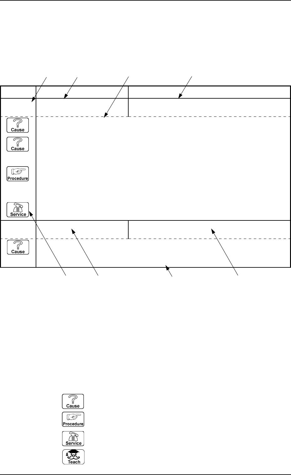
Error Code Display A Display B
(Cause 1) The sensor may be defective.
(NEXT PAGE)
0D 01 01 BPC-AXIS ORIGIN ENCORDER ORIGIN WAS NOT DETECTED.
0D 01 02 BPC-AXIS ORIGIN ORIGIN (SLIDE) WAS NOT DETECTED.
;BPH163 E / R
*1: Shows an ERROR code.
The description is shown according to the order of the code No.
*2: Shows the description of “Section A Indication” for the ERROR code.
*3: Shows the description of “Section B Indication” for the ERROR code.
*4: Shows the “Cause” and “Remedy” for the ERROR code.
Note: The description might be different from that in the “CAUSE AND REM-
EDY” section on the error display.
*5: When the description is continued on to the next page, “NEXT PAGE” is
shown.
*6: Icons
: Indicates the cause of the error.
: Indicates the work procedure.
: Contact our service personnel.
: Shows the teaching function.
*1 *2 *4 *3
*2
*6
*5
*3
Indication Example