OM-1068-001.pdf - 第140页
Tg0252-PM-SO 991 1-001 Chapter 1 3-11 4. Matrix Change Operations • The location (matrix) of the component to be picked up subsequently can be changed. When the [MA TRIX CHANGE] key is pressed at the “LINE MODE” display …
Tg0252-PM-SO
9911-001 Chapter 1 3-10
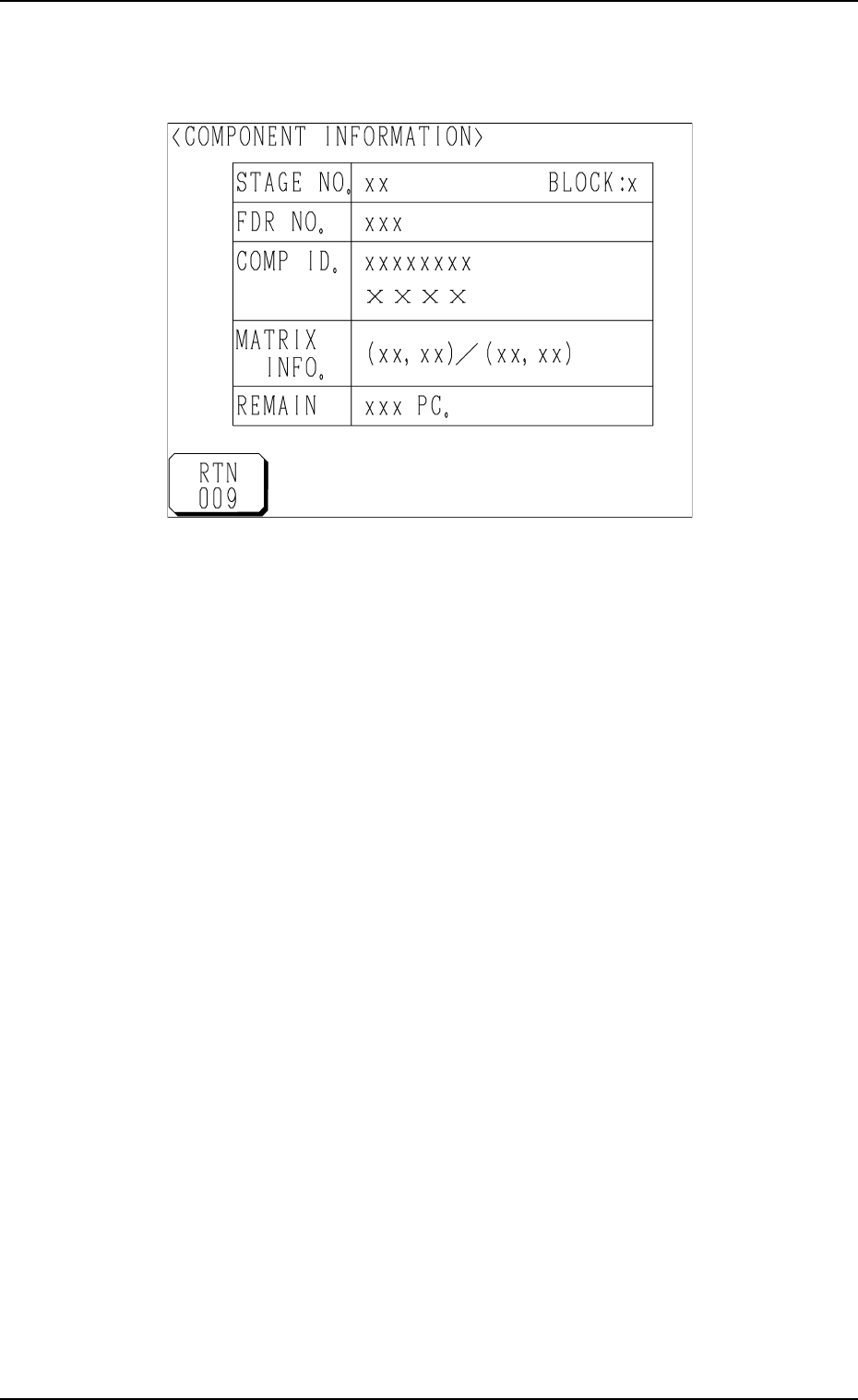
(2) Press the block No. key desired to check the component information.
The component information related to the selected No. is displayed as
shown below.
Fig. 1.63
STAGE NO. : This shows the selected stage No.
BLOCK : This shows the selected block No.
FDR NO. : This shows a feeder No. (type of components).
COMP ID. : This shows a component ID.
MATRIX INFO. : This shows “Location (Coordinates) of Subsequently
Picked Component/Matrix Size”.
REMAIN : This shows the quantity of remaining components
related to the currently indicated stage and block Nos.
3. Component Information
Tg0252-PM-SO
9911-001 Chapter 1 3-11
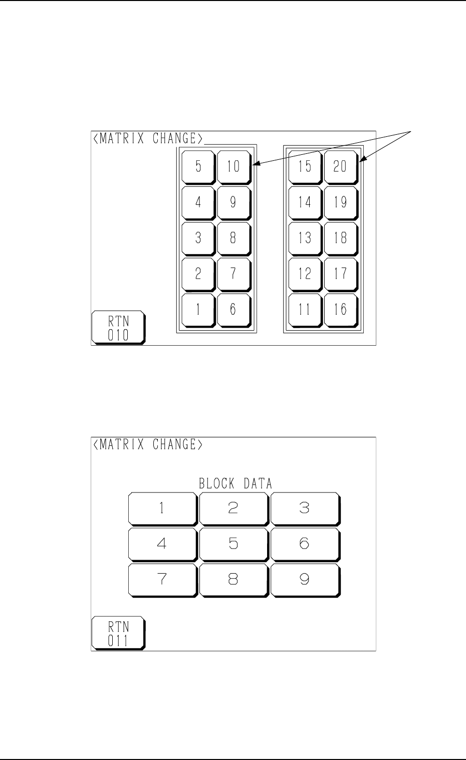
4. Matrix Change Operations
• The location (matrix) of the component to be picked up subsequently can be
changed.
When the [MATRIX CHANGE] key is pressed at the “LINE MODE” display
(Fig. 1.57), the following display appears on the screen.
Fig. 1.65
Fig. 1.64
(1) Select the stage on which the matrix of the component to be picked up
subsequently must be changed.
Press the stage No. keys *1. The following display appears on the screen.
*1
4. Matrix Change Operations
Tg0252-PM-SO
9911-001 Chapter 1 3-12
(2) Press the block No. key related to the location in matrix to be changed at
the display (Fig. 1.65).
The “MATRIX CHANGE” display related to the selected block appears
on the screen as shown in Fig. 1.66.
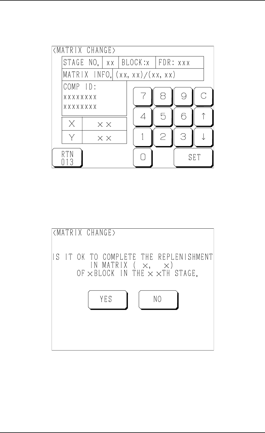
Fig. 1.67
(4) Select the [YES] or the [NO] key to make the set parameters valid or
invalid.
[YES]: The changed matrix values become valid.
[NO]: The original matrix values are not changed.
Fig. 1.66
(3) Enter matrix values (X and Y), using the ten-key pad and press the [SET]
key.
Another “MATRIX CHANGE” display (Fig. 1.67) appears on the screen
for the confirmation of the set parameters.
4. Matrix Change Operations