OM-1068-001.pdf - 第264页
Chapter 5 2-7 Tg0252-PM-SO 2.5 SDS IN 2 2. Electrical Circuit Diagrams Upper Magazine Clutch Connection Forward Limit Upper Magazine Clutch Connection Backward Limit Upper Magazine Presence Check Lower Magazine Clutch Co…
Chapter 5 2-6 Tg0252-PM-SO
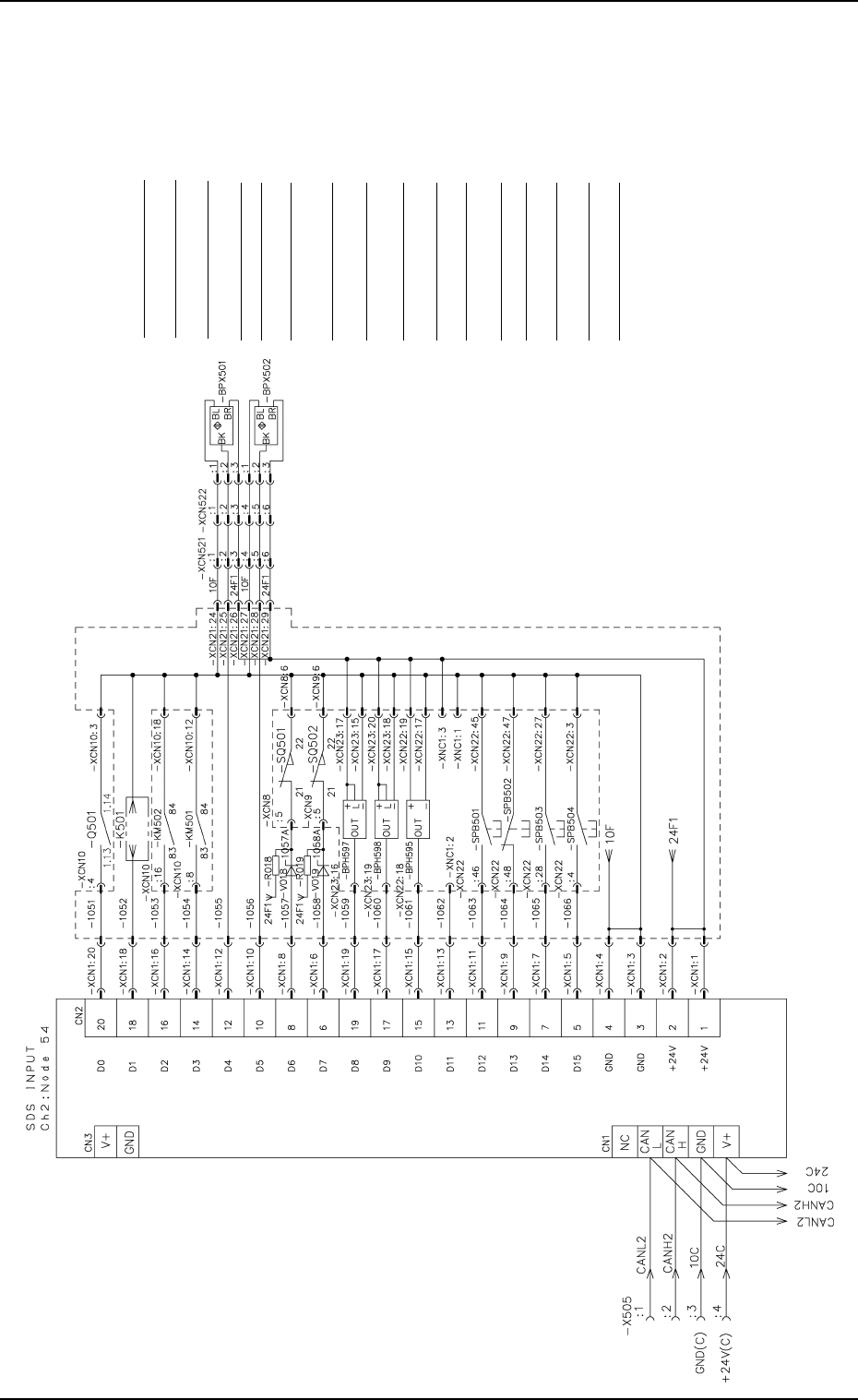
2.4 SDS IN 1
2. Electrical Circuit Diagrams
Notes : (a) It shows the diagram within dotted lines is within the relay PCB.
(b) Note 1 shows the diagram without dotted lines is within the relay
PCB.
(c) For the diode in Note 2, DS446 is used.
Resistances -R018 and -R019: 470Ω, 6W
Note.1
Note.2
Note.1
Circuit Breaker OFF
Elevator Safety Relay ON
Servomotor Power-Up Check (1)
Servomotor Power-Up Check (2)
Upper Magazine Base Connection Check
Lower Magazine Base Connection Check
Upper Door Electromagnetic Switch
Lower Door Electromagnetic Switch
Pallet Stopper Cancellation
Pallet Direction Detection
Reserved
Start Switch (MOVE)
Stop Switch (STOP)
U READY Switch
(U READY)
L READY switch
(L READY)
Cylinder Backward Limit
Note.2
Note.1
0112-004A(M742WTR--2104)
Chapter 5 2-7 Tg0252-PM-SO
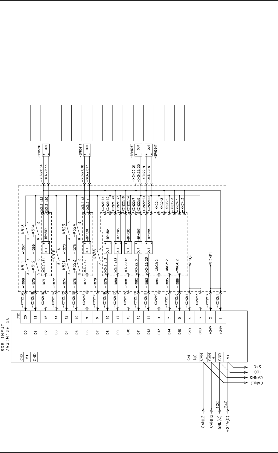
2.5 SDS IN 2
2. Electrical Circuit Diagrams
Upper Magazine Clutch Connection
Forward Limit
Upper Magazine Clutch Connection
Backward Limit
Upper Magazine Presence Check
Lower Magazine Clutch Connection
Forward Limit
Lower Magazine Clutch Connection
Backward Limit
Lower Magazine Detection Check
Lower Magazine Presence Check
Elevator Shaft Intermediate Position Overrun (+)
Elevator Shaft Intermediate Position Overrun (-)
Pallet Projection Check (1)
Pallet Presence Check (Upper)
Pallet Presence Check (Lower)
Type Code (1)
Type Code (2)
Type Code (3)
Supplied
from the
SDS board
Upper Magazine Normal Position Check
Note.1
Note.1
Note.1
Notes : (a) It shows the diagram within dotted lines is within the
relay PCB.
(b) Note 1 shows the diagram without dotted lines is
within the relay PCB.
0010-002-(M742WTR--2105)
Chapter 5 2-8 Tg0252-PM-SO
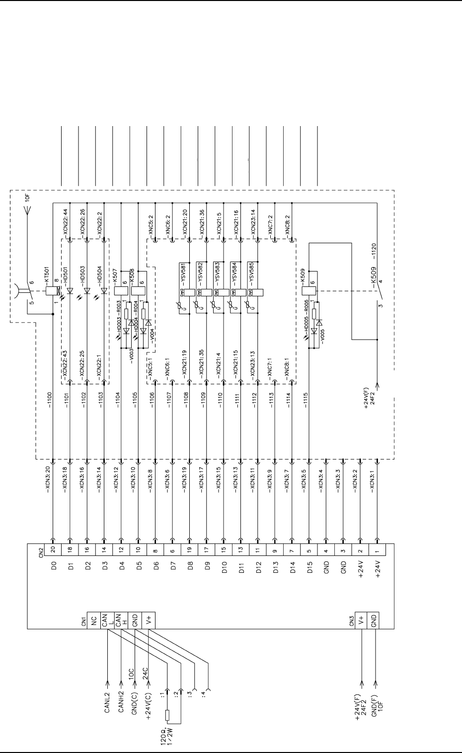
2.6 SDS OUT 1
2. Electrical Circuit Diagrams
Elevator Shaft Power Source
Operation Switch (MOVE) LED
U READY Switch (U READY) LED
L READY Switch (L READY) LED
Upper Door Electromagnetic Lock
Lower Door Electromagnetic Lock
Reserved
Reserved
Upper Magazine (1) Clutch Connection
Upper Magazine (2) Clutch Connection
Lower Magazine (1) Clutch Connection
Lower Magazine (2) Clutch Connection
Pallet Stopper Cancellation
Reserved
Reserved
Output Power ON
Note.1
Note.1
Notes : (a) It shows the diagram within dotted lines is within the
relay PCB.
(b) Note 1 shows the diagram without dotted lines is
within the relay PCB.
0010-002-(M742WTR-2106)