OM-1068-001.pdf - 第127页
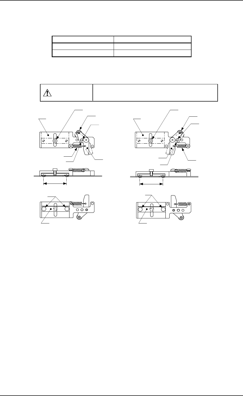
MF-5050L (For MG-5050L) 30 φ 3.1 Hole (For Lever) Roller Anchor Bolt Base Lever Spring Clamping Claw Clamp Block MF-5050R (For MG-5050R) 30 Roller Anchor Bolt φ Lever Spring Clamping Claw Clamp Block 3.1 Hole (For Lever)…
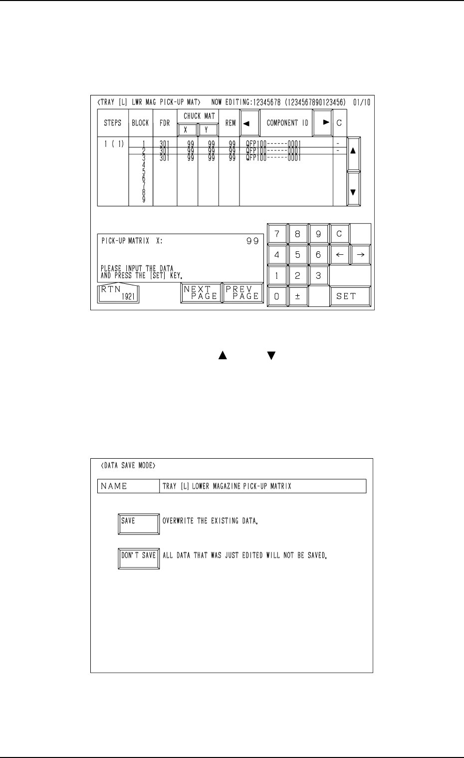
• Case: The machine is in the “STOP” or the “PAUSE” mode
Shown are the matrix positions of the tray components to be chucked subse-
quently. (Fig. 1.50)
The matrix can be changed while the machine is in the “STOP” or the
“PAUSE” mode.
Fig. 1.51
Fig. 1.50
To change the matrix, press the [ ] or the [ ] key to select the related block.
Select the [X] or the [Y] key, use the ten-key pad to specify the matrix posi-
tion, and press the [SET] key to define the parameters.
After the matrix position is defined, press the [RTN] key.
The “DATA SAVE MODE” display (Fig. 1.51) appears on the screen. To save
the changed matrix position, press the [SAVE] key. Otherwise, press the
[DON’T SAVE] key.
11. Others
0010-003 Chapter 1 2-43 Tg0252-PM-SO
MF-5050L (For MG-5050L)
30
φ
3.1 Hole
(For Lever)
Roller
Anchor Bolt
Base
Lever
Spring
Clamping Claw
Clamp Block
MF-5050R (For MG-5050R)
30
Roller
Anchor Bolt
φ
Lever
Spring
Clamping Claw
Clamp Block
3.1 Hole
(For Lever)
Base
( 5.5)φ
( 5.5)φ
φ 3.1 Hole (For Base)
φ
3.1 Hole (For Base)
11.2 Tray Fixing Metals
• There are two kinds of tray fixing metals and each is labeled.
• The tray fixing metal can be used for both magazine types “MG-5050L” and
“MG-5050R” by rearranging the parts of the lever section.
CAUTION
Do not make a mistake of selecting the wrong
direction of the tray fixing metal.
Unit: mm
Fig. 1.52 Appearance of Tray Fixing Metal
11. Others
0112-003 Chapter 1 2-44 Tg0252-PM-SO
Types of Magazines Types of Tray Fixing Metals
MG-5050L MF-5050L (TL)
MG-5050R MF-5050R (TR)

Procedure for Inversion (leftside right) of Tray Fixing Metal
Note: When the tray fixing metal is used after the parts of the lever section
are rearranged, it must be re-labeled to avoid any mistake in determin-
ing the direction (right or left).
(1) Remove the screw fastening the lever to the base with a Phillips-type
screwdriver.
(2) Remove the screw fastening the spring to the base with a Phillips-type
screwdriver.
(3) Rearrange the direction of the lever.
(4) Fasten the lever to the base with the screw.
• Fasten the lever to “A” in Fig. 1.53 for MG-5050L.
• Fasten the lever to “B” in Fig. 1.53 for MG-5050R.
Fig. 1.53 Position where the lever and the spring should be fastened
(5) Fasten the spring to the base with the screw.
• Engage the spring with “C” in Fig. 1.53 for MG-5050L.
• Engage the spring with “D” in Fig. 1.53 for MG-5050R.
11. Others
0010-002 Chapter 1 2-45 Tg0252-PM-SO
A
C
D
B