OM-1068-001.pdf - 第126页
• Case: The machine is in the “STOP” or the “P AUSE” mode Shown are the matrix positions of the tray components to be chucked subse- quently . (Fig. 1.50) The matrix can be changed while the machine is in the “STOP” or t…
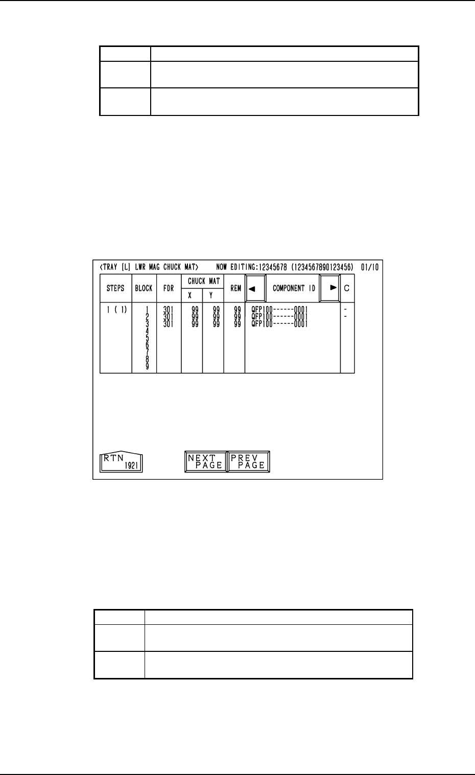
Background Color of Block Feeder Nos. (FDR. NO.)
Shown are the feeder Nos. (FDR. NO.), the chuck matrix positions, the re-
maining number of components, and the component IDs which belong to each
individual blocks.
Foreground Color of Feeder Nos. (FDR. NO.)
(3) When an arbitrary “STEPS” key is pressed, the “TRAY [L] LWR MAG
CHUCK MAT” display (the display for matrix indication/change) ap-
pears on the screen.
• Case: The machine is in the “RUN” mode (including the “WAIT” mode)
Shown are the matrix positions of the tray components to be picked up sub-
sequently. (Fig. 1.49)
The matrix cannot be changed while the machine is running.
11. Others
Fig. 1.49
Red This indicates that the block is short of components.
Green
This indicates that the block is used in the current
pattern program.
Black
This indicates that the block is not used in the current
pattern program.
Red This indicates that the block is short of components.
Green
This indicates that the block is used in the current
pattern program.
White
This indicates that the block is not used in the current
pattern program.
Table 1.8
Table 1.7
0010-002 Chapter 1 2-42 Tg0252-PM-SO
• Case: The machine is in the “STOP” or the “PAUSE” mode
Shown are the matrix positions of the tray components to be chucked subse-
quently. (Fig. 1.50)
The matrix can be changed while the machine is in the “STOP” or the
“PAUSE” mode.
Fig. 1.51
Fig. 1.50
To change the matrix, press the [ ] or the [ ] key to select the related block.
Select the [X] or the [Y] key, use the ten-key pad to specify the matrix posi-
tion, and press the [SET] key to define the parameters.
After the matrix position is defined, press the [RTN] key.
The “DATA SAVE MODE” display (Fig. 1.51) appears on the screen. To save
the changed matrix position, press the [SAVE] key. Otherwise, press the
[DON’T SAVE] key.
11. Others
0010-003 Chapter 1 2-43 Tg0252-PM-SO
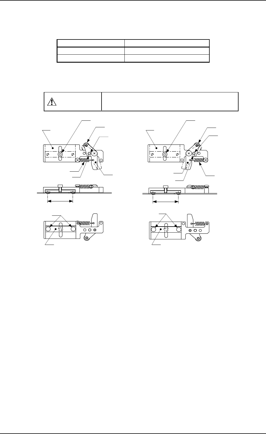
MF-5050L (For MG-5050L)
30
φ
3.1 Hole
(For Lever)
Roller
Anchor Bolt
Base
Lever
Spring
Clamping Claw
Clamp Block
MF-5050R (For MG-5050R)
30
Roller
Anchor Bolt
φ
Lever
Spring
Clamping Claw
Clamp Block
3.1 Hole
(For Lever)
Base
( 5.5)φ
( 5.5)φ
φ 3.1 Hole (For Base)
φ
3.1 Hole (For Base)
11.2 Tray Fixing Metals
• There are two kinds of tray fixing metals and each is labeled.
• The tray fixing metal can be used for both magazine types “MG-5050L” and
“MG-5050R” by rearranging the parts of the lever section.
CAUTION
Do not make a mistake of selecting the wrong
direction of the tray fixing metal.
Unit: mm
Fig. 1.52 Appearance of Tray Fixing Metal
11. Others
0112-003 Chapter 1 2-44 Tg0252-PM-SO
Types of Magazines Types of Tray Fixing Metals
MG-5050L MF-5050L (TL)
MG-5050R MF-5050R (TR)