OM-1068-001.pdf - 第232页
Chapter 4 1-5 Tg0252-PM-SO 4. Maintenance (Every 3 Months after Initial Month) T able 4.3 Fig. 4.2 Elevator Shaft of FP-5021L (Same to “FP-5021R”) 4. Maintenance (Every 3 Months after Initial Month) DANGER • Be sure to s…
Chapter 4 1-4 Tg0252-PM-SO
3. Monthly Maintenance
Table 4.2
Fig. 4.1 MP-5050
Note: (a) The component pick-up rate may deteriorate when the pallet has a
warpage.
(b) If the tape has partly peeled off on the pallet side surface or rear
side surface, apply an adhesive agent and affix it.
If the tape is worn or peeled off completely, contact our Sales De-
partment or our agent.
3. Monthly Maintenance
Maintenance Spot
REF
DWG
Description Required Item Check
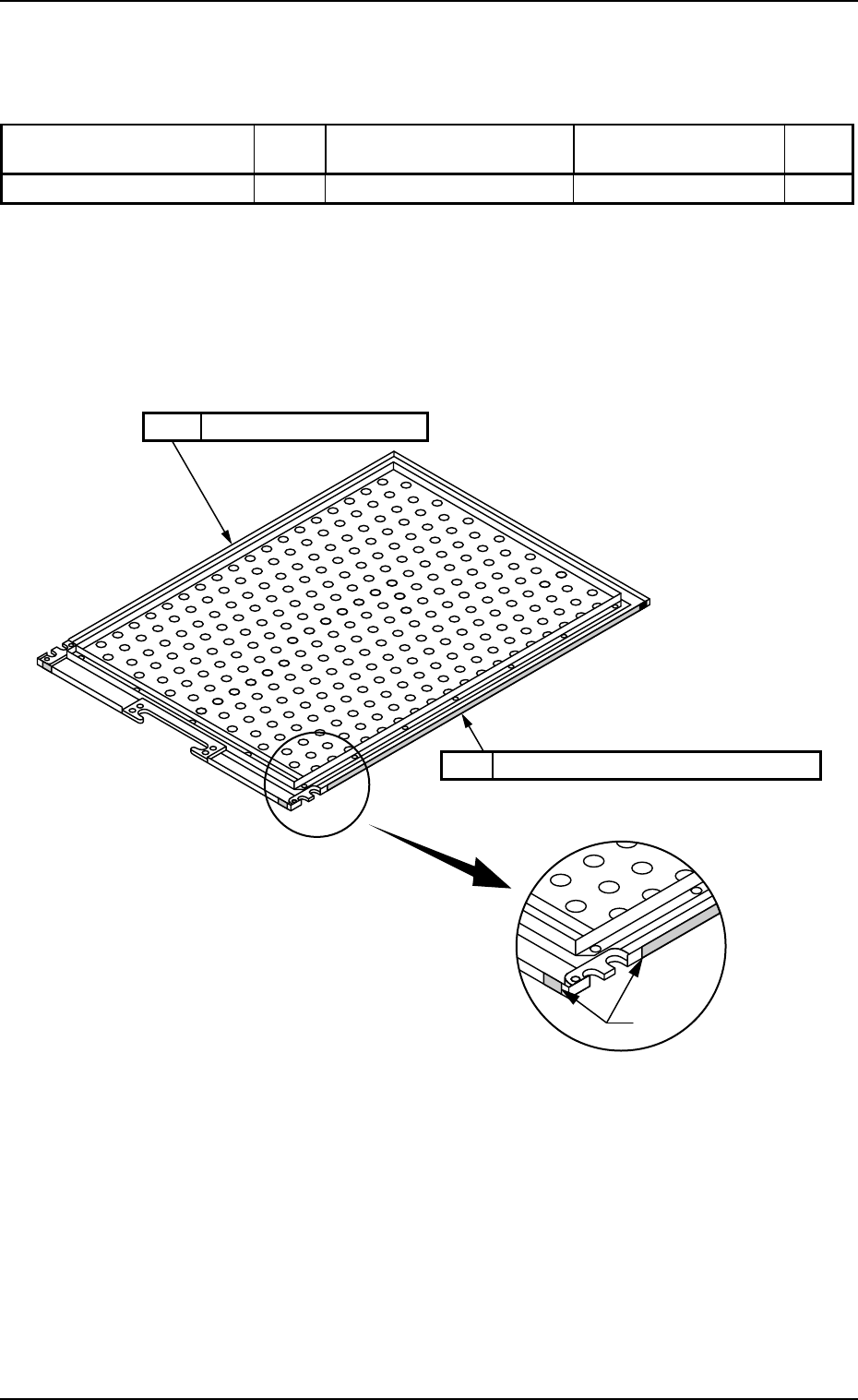
Pallet Fig. 4.1 Cleaning and Damage Check Rag
Pallet
Damage Check and Cleaning (Rag)
Tape
Pallet
Check the tape for peel-off on the side and rear side.
0112-002
Chapter 4 1-5 Tg0252-PM-SO
4. Maintenance (Every 3 Months after Initial Month)
Table 4.3
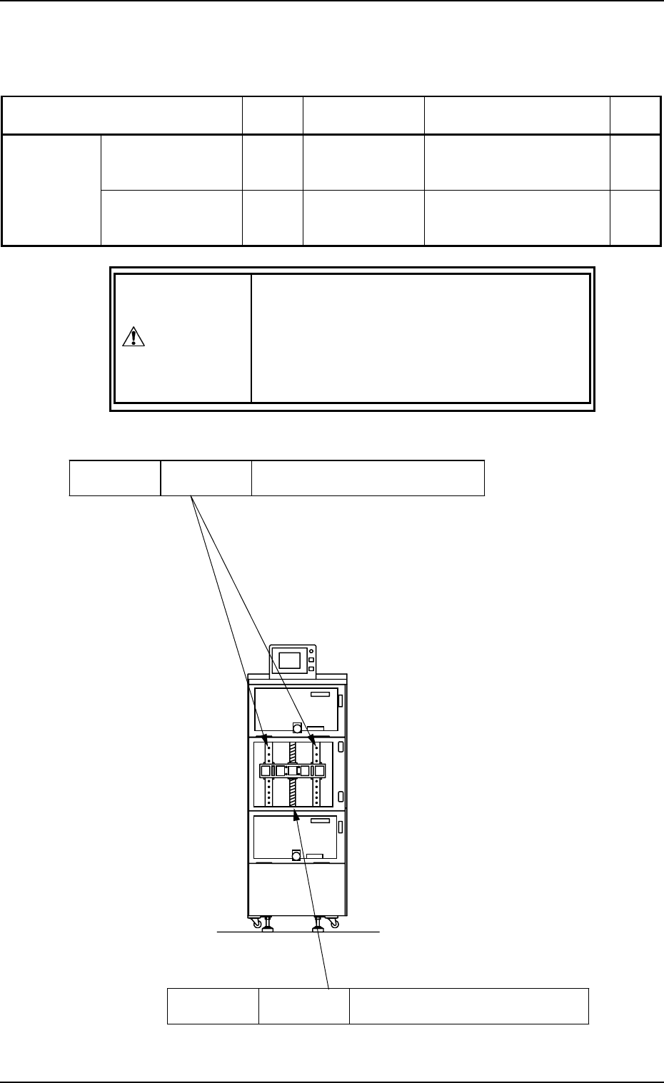
Fig. 4.2 Elevator Shaft of FP-5021L (Same to “FP-5021R”)
4. Maintenance (Every 3 Months after Initial Month)
DANGER
• Be sure to shut off the power before detach-
ing the center cover of the multi-layer tray
feeder.
• Do not supply power to the machine or per-
form any operations with the center cover be-
ing detached.
Elevator
Shaft
Linear Way
Cleaning (Oiled Rag) and Lubrication
(DAPHNE EPONEX GREASE No. 1)
Ref.: The center cover must be detached to apply
grease to the elevator shaft.
Refer to “5. Detachment and Attachment of
Center Cover of Section 1 in Chapter 4” for the
detailed information on how to detach the cen-
ter cover.
Elevator
Shaft
Ball Screw
Cleaning (Oiled Rag) and Lubrication
(DAPHNE EPONEX GREASE No. 1)
Maintenance Spots
REF
DWG
Description Required Items Check
Ball Screw Fig. 4.2 Cleaning and
Lubrication
Oiled Rag, DAPHNE
EPONEX GREASE No. 1,
and Brush
Elevator Shaft
Linear Way Fig. 4.2 Cleaning and
Lubrication
Oiled Rag, NEW
MOLYNOC GREASE No.
1, Brush
9911-001
Chapter 4 1-6 Tg0252-PM-SO
5. Detachment and Attachment of Center Cover
DANGER
• When the center cover of multi-layer tray
feeder is detached, the load power is shut
off.
• Do not supply power to the machine or per-
form any operations with the center cover be-
ing detached.
5.1 Detachment
(1) Zero the multi-layer tray feeder.
Refer to “2. Zeroing Operation of Section 4 in Chapter 1” for details.
(2) Separate the upper and lower magazines from the elevator shaft.
Refer to “3.1 ELEVATOR UNIT Display of Section 4 in Chapter 1” for
details.
(3) Remove the setscrews (4 locations) fastening the center cover with a
Phillips-type screwdriver. (See Fig. 4.3.)
The center cover can be detached.
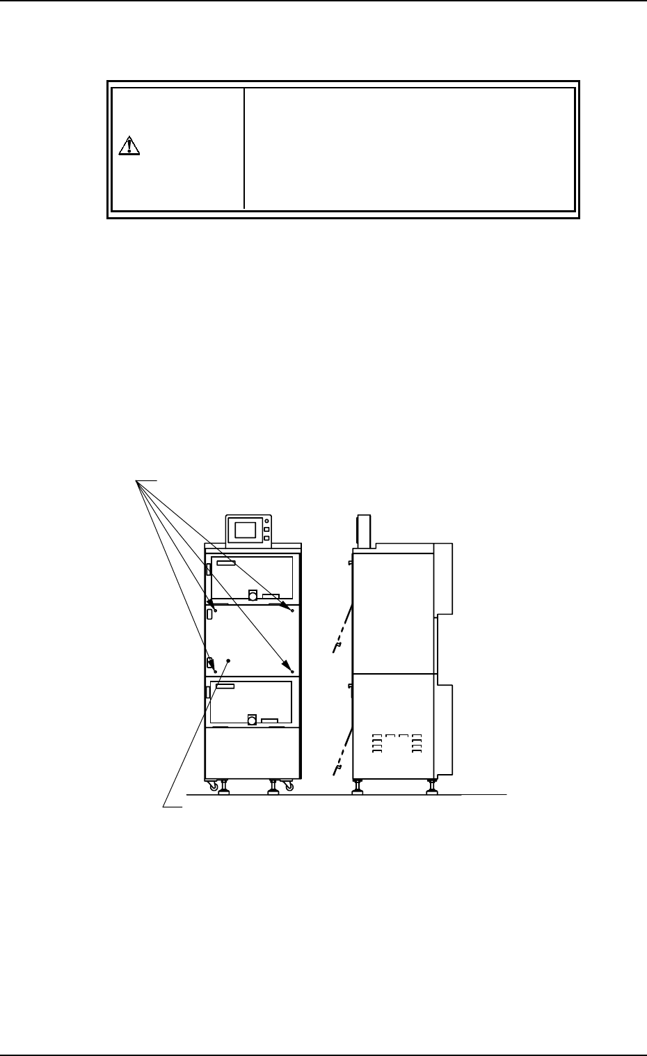
Fig. 4.3 FP-5021L (Same to “FP-5021R”)
5.2 Attachment
(1) Align the screw holes of the center cover with the screw holes of the
multi-layer tray feeder.
(2) Hold the center cover in position and fasten it securely with setscrews
(4 locations), using a Phillips-type screwdriver.
5. Detachment and Attachment of Center Cover
Setscrews fastening the center cover (4 locations)
Center Cover
0005-002