OM-1068-001.pdf - 第177页
01 12-001 C h ap t er 3 2-16 Tg0252-PM-SO 4. Troubleshooting after Error Message 1 1 05 0 B TV1-AXIS INTERLOCK CARRIAGE NOT DREW NORMALL Y . 1 1 05 0D TV1-AXIS INTERLOCK SPECIFIED STORED CARRIAGE NOT DETECTED. Error Code…
0112-001 Chapter 3 2-15 Tg0252-PM-SO
4. Troubleshooting after Error Message
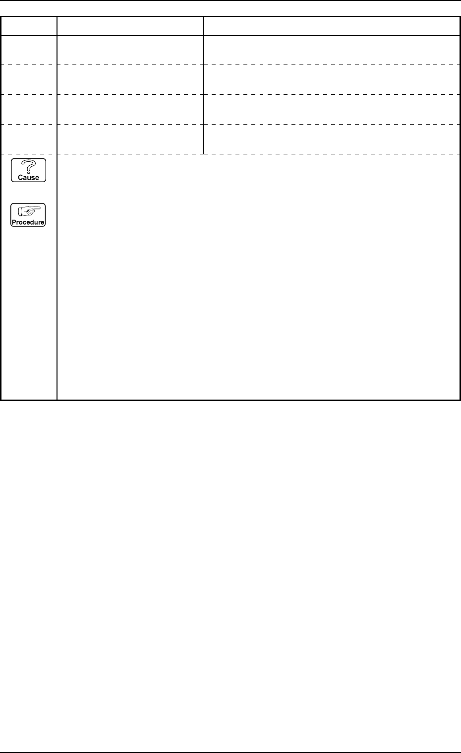
11 05 07 TV1-AXIS INTERLOCK CHUTE CARRIAGE CHECK #1 (LOWER) [BPH270]
DETECTED.
11 05 07 TV1-AXIS INTERLOCK CHUTE CARRIAGE CHECK #2 (LOWER) [BPH271]
DETECTED.
Error Code Display A Display B
11 05 08 TV1-AXIS INTERLOCK CHUTE CARRIAGE CHECK #3 (LOWER) [BPH272]
DETECTED.
11 05 0A TV1-AXIS INTERLOCK CHUTE CARRIAGE CHECK #4 (LOWER) [BPH273]
DETECTED.
(Cause 1) Is there any foreign substance on the chute?
(Reset Procedure in the case of Cause 1)
Reset Procedure
(1) Press the [CLEAR ALARM] key to stop the buzzer sound.
(2) Press the [RESET] key to cancel the error indication.
(3) Press the [READY] button on the operation panel on the side of the beam A to turn off the
LED for the [READY] button.
(4) Press the [EMERGENCY STOP] button to turn off the load power, then open the supply cover
on the side of the beam A. Take the greatest care for safety.
(5) Remove any foreign substance, such as a projected component, which caused the error.
(6) Close the supply cover and press the [POWER] button to turn on the load power.
(7) Press the [READY] button on the side of the beam A to turn on the LED for the [READY]
button.
(8) Press the [ZERO] button to return all axes to their original positions. Continue production
according to the “WARM Start Operation Procedure”.
0112-001 Chapter 3 2-16 Tg0252-PM-SO
4. Troubleshooting after Error Message
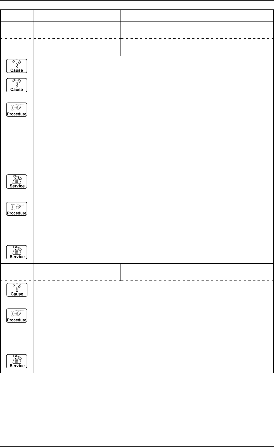
11 05 0B TV1-AXIS INTERLOCK CARRIAGE NOT DREW NORMALLY.
11 05 0D TV1-AXIS INTERLOCK SPECIFIED STORED CARRIAGE NOT DETECTED.
Error Code Display A Display B
(Cause 1) There might be an error in the palette or the chute section palette detection sensor.
(Reset Procedure in the case of Cause 1)
Reset Procedure
(1) Press the [CLEAR ALARM] key to stop the buzzer sound.
(2) Press the [RESET] button to cancel the error mode.
(3) Press the [ZERO] button to return all axes to their original positions. Continue the production
according to the “WARM Start Operation Procedure”.
(4) If the device can’t be reset after the above procedure, contact our service personnel.
11 05 0C TV1-AXIS INTERLOCK CARRIAGE NOT STORED NORMALLY.
(Cause 1) An incorrect value might be input for the tray height data.
(Cause 2) There might be an error in the pulling level and chute section pallet detection sensors.
(Reset Procedure in the case of Cause 1)
Reset Procedure
(1) Press the [CLEAR ALARM] key to stop the buzzer sound.
(2) Press the [RESET] key to cancel the error mode.
(3) Open the “Component Library [Component Supply]” display.
(4) Check the tray height data item on the component library data. If the data value is not correct,
set the actual height data value correctly.
(5) Press the [ZERO] button to return all axes to their original positions.
(6) Re-start.
(7) If the device can’t be restarted, contact our service personnel.
(Reset Procedure in the case of Cause 2)
Reset Procedure
(1) Press the [CLEAR ALARM] key to stop the buzzer sound.
(2) Press the [RESET] button to cancel the error mode.
(3) Press the [ZERO] button to return all axes to their original positions. Continue the production
according to the “WARM Start Operation Procedure”.
(4) If the device can’t be reset after the above procedure, contact our service personnel.
0112-001 Chapter 3 2-17 Tg0252-PM-SO
4. Troubleshooting after Error Message
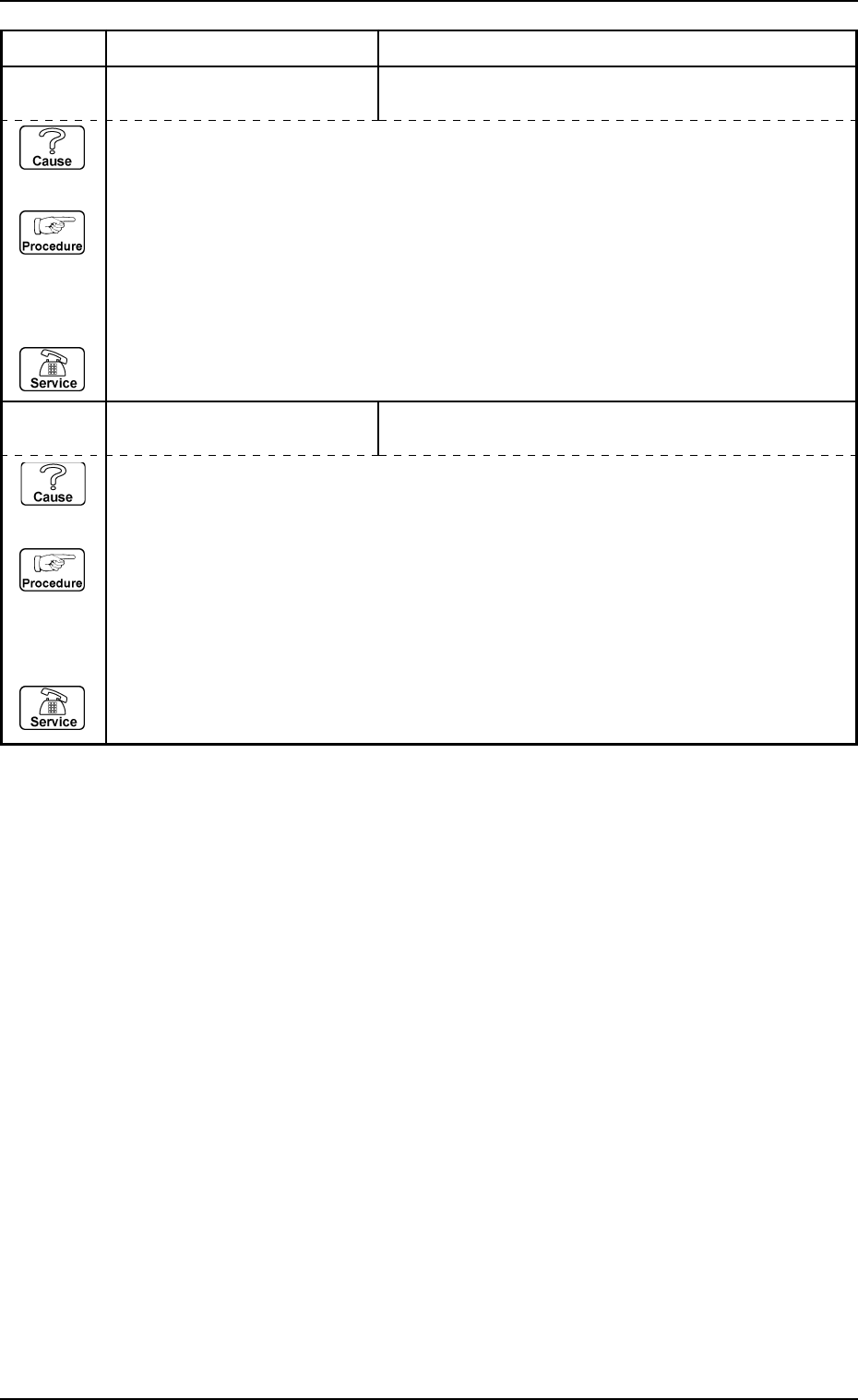
11 05 0E TV1-AXIS INTERLOCK THERE IS CARRIAGE IN THE STORED STEP.
11 05 0F TV1-AXIS INTERLOCK SPECIFIED DRAWN CARRIAGE NOT DETECTED.
Error Code Display A Display B
(Cause 1) This is the device’s self-diagnostic message.
(Reset Procedure in the case of Cause 1)
Reset Procedure
(1) Press the [CLEAR ALARM] key to stop the buzzer sound.
(2) Press the [RESET] button to cancel the error mode.
(3) Press the [ZERO] button to return all axes to their original positions. Continue the production
according to the “WARM Start Operation Procedure”.
(4) If the device can’t be reset after the above procedure, contact our service personnel.