OM-1068-001.pdf - 第13页
01 12-002 12 Tg0252-PM-SO About Precaution Labels About Safety Precaution Labels • The following warning signs are classified into three categories according to the degree of danger . Please fully understand the meaning …

Contents
Page
0112-002 11 Tg0252-PM-SO
2.1 Electrical Circuit Diagrams
(Electrical and Electronic Symbols) ..................... Chapter 5 1- 3
2.2 Elevator Circuit Diagrams........................................ Chapter 5 1-10
2.3 Power Supply Circuit Diagram 1 ............................. Chapter 5 1- 11
2.4 Power Supply Circuit Diagram 2 ............................. Chapter 5 1-12
2.5 SDS IN 1.................................................................. Chapter 5 1-13
2.6 SDS IN 2.................................................................. Chapter 5 1-14
2.7 SDS OUT 1.............................................................. Chapter 5 1-15
2.8 Operation Monitor Circuit Diagram.......................... Chapter 5 1-16
3. Location of Sensors, Switches, and Loades ................. Chapter 5 1-17
4. Parts Location (FP-5021L) ............................................ Chapter 5 1-18
4.1 Whole View Layout .................................................. Chapter 5 1-18
4.2 Power Supply Section Layout ................................. Chapter 5 1-19
4.3 Relay PCB Layout ................................................... Chapter 5 1-20
4.4 Operation Panel Layout........................................... Chapter 5 1-21
Section 2 Material (FP-5021R) ............................................. Chapter 5 2- 1
1. Air Piping Diagram (FP-5021R) .................................... Chapter 5 2- 2
2. Electrical Circuit Diagrams ............................................ Chapter 5 2- 3
2.1 Elevator Circuit Diagram ......................................... Chapter 5 2- 3
2.2 Power Supply Circuit Diagram 1 ............................. Chapter 5 2- 4
2.3 Power Supply Circuit Diagram 2 ............................. Chapter 5 2- 5
2.4 SDS IN 1.................................................................. Chapter 5 2- 6
2.5 SDS IN 2.................................................................. Chapter 5 2- 7
2.6 SDS OUT 1.............................................................. Chapter 5 2- 8
2.7 Operation Monitor Circuit Diagram.......................... Chapter 5 2- 9
3. Location of Sensors, Switches, and Loads ................... Chapter 5 2-10
4. Parts Location (FP-5021R) ........................................... Chapter 5 2- 11
4.1 Whole View Layout .................................................. Chapter 5 2- 11
4.2 Power Supply Section Layout ................................. Chapter 5 2-12
4.3 Relay PCB Layout ................................................... Chapter 5 2-13
4.4 Operation Panel Layout........................................... Chapter 5 2-14
0112-002 12 Tg0252-PM-SO
About Precaution Labels
About Safety Precaution Labels
• The following warning signs are classified into three categories
according to the degree of danger.
Please fully understand the meaning of each sign for safety pre-
cautions.
• Identifying Alert Icons
: This symbol mark represents danger or prompts warning.
: This symbol mark represents prohibited operations.
: This symbol mark represents forced operations or instructions.
This indicates a potentially hazardous situation
which, if not avoided, could result in death or seri-
ous injury.
WARNING
This indicates a potentially hazardous situation
which, if not avoided, may result in injury or physi-
cal damage.
CAUTION
DANGER
This indicates an imminently hazardous situation
which, if not avoided, will result in death or serious
injury.
Checking Item
xx
xx
x
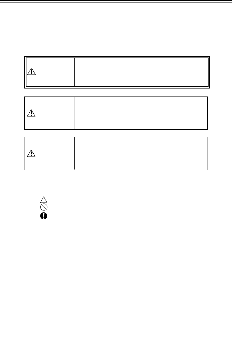
Dangers resulting from Relocation or Resale
(1) Lowering Safety Level or Quality
0304-003 16 Tg0252-PM-SO
3. Relocation and/or Resale of the Device
x If you intend to relocate or resell the device to a third party, always
contact our marketing department or sales agency beforehand.
x If relocation or resale is done without our
written consent, we shall not be responsible
for the results.
Contact
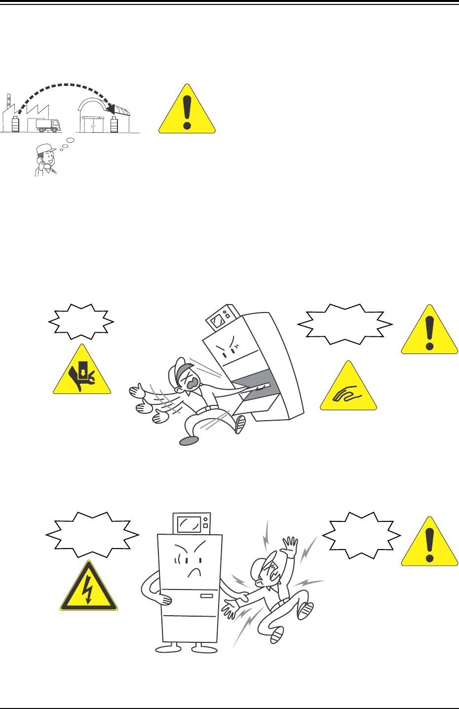
Example: Abnormalities caused by Noise
Example: Imperfect Contact/Wiring Error, etc.
Injury
Malfunction
Electric
Shock
Short Circuit
WARNING
WARNING
CAUTION
x Before setting up a resold and/or transferred machine, please ask
our service personnel or agency for safety inspections.