OM-1068-001.pdf - 第96页
5. Preparation and Confirmation before Operation Tg0252-PM-SO (3) While keeping the lever at the standard position, insert the pins, etc., into the f 3.1 holes to temporarily lock the lever such that the lever does not r…
5. Preparation and Confirmation before Operation
Tg0252-PM-SO
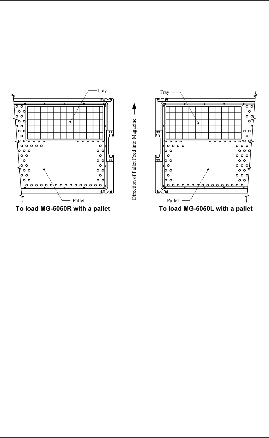
5.2.1.2 Tray Attachment to Pallet
(1) Put a tray on the pallet.
• To load MG-5050L with a pallet
Put a tray on the rear left side of the pallet.
• To load MG-5050R with a pallet
Put a tray on the rear right side of the pallet.
Note: Don't make an error about the front and rear of the pallet.
Fig. 1.16 Position of Tray on Pallet (Top View)
0010-001 Chapter 1 2-14-2
5. Preparation and Confirmation before Operation
Tg0252-PM-SO
(3) While keeping the lever at the standard position, insert the pins, etc., into
the f 3.1 holes to temporarily lock the lever such that the lever does not
return.
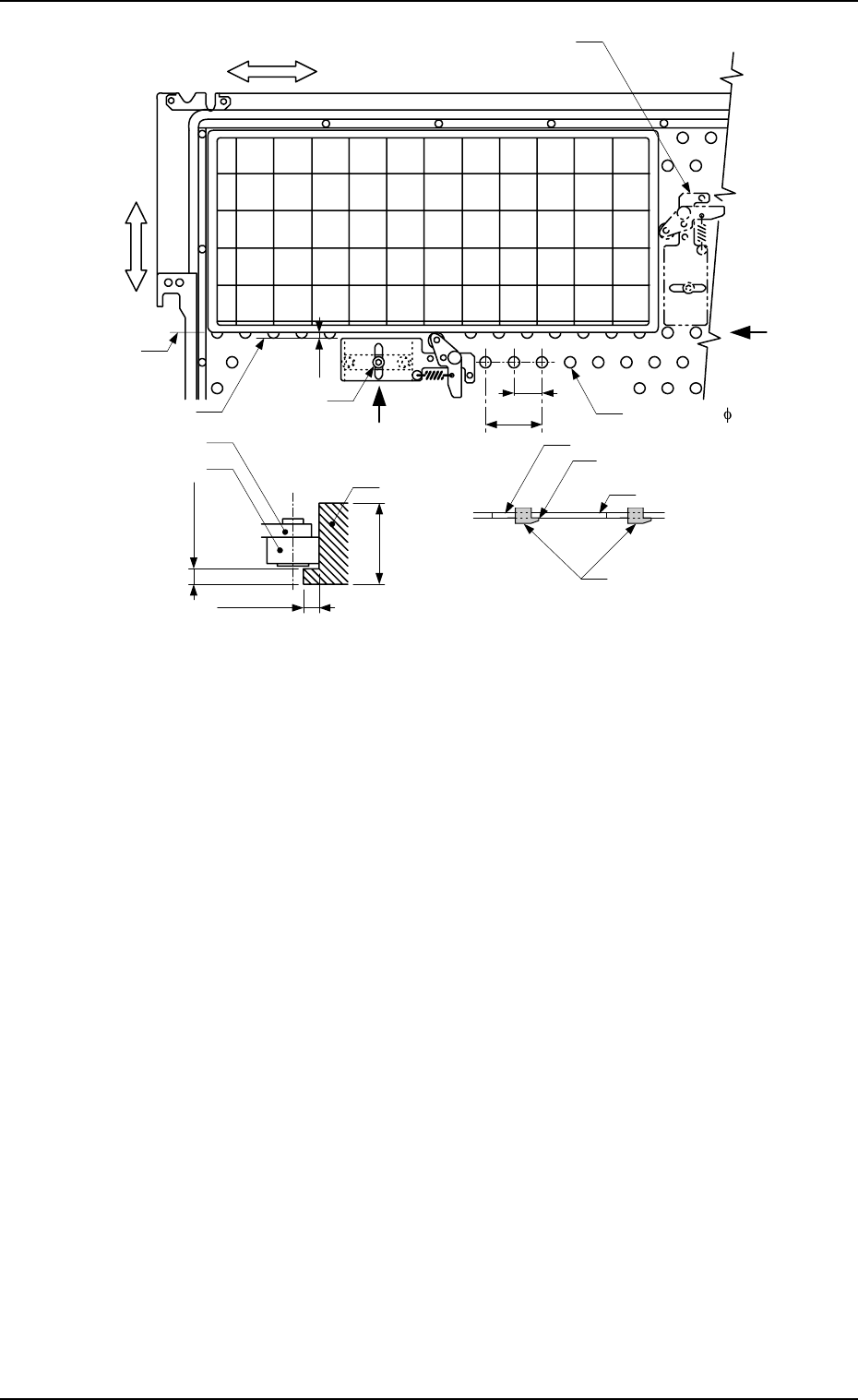
(4) Fasten the tray fixing metal to the pallet along the longer side of the tray.
· Positioning
The roller of the tray fixing metal should be located at the position close
to the center of the longer side of the tray and the clearance between
the end planes of the base and the tray should become approximately
2.5 mm.
Note: When a tray fixing metal cannot be attached along the longer
side of the tray, it should be mounted close to the center of the
shorter side.
· Locking
Tighten the anchor bolt while the clamping claw of the tray fixing metal
is engaged with the anchor hole on the pallet (View B in Fig. 1.18).
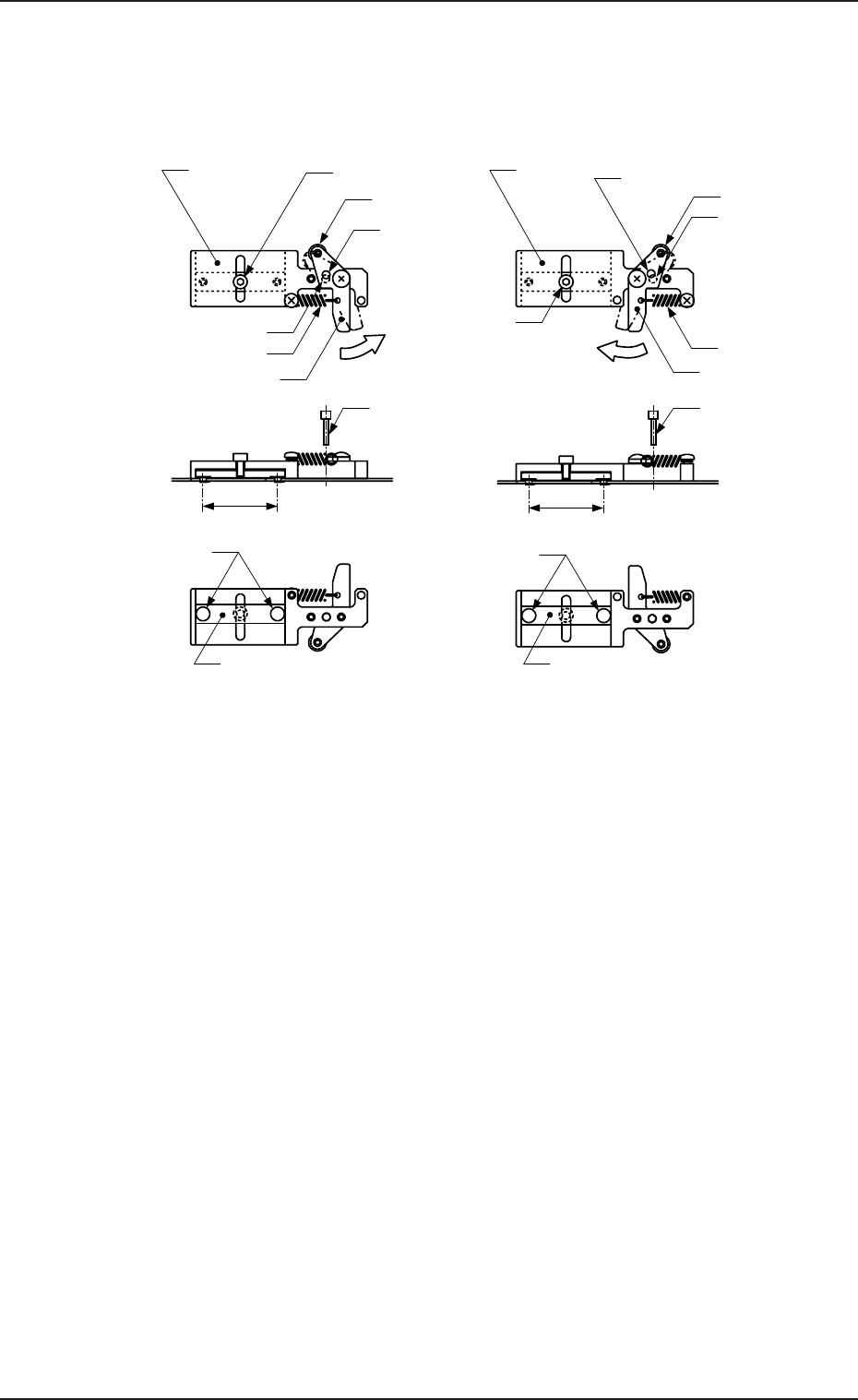
Fig. 1.17 Tray Fixing Metals
(2) Push the lever of the tray fixing metal in the arrow direction and hold it at
the position where the f 3.1 hole of the lever aligns with the f 3.1 hole of
the base.
This position is called “Standard Position”.
Roller
Anchor Bolt
Lever
Spring
Roller
Anchor Bolt
Base
f
3.1 Hole
(For Lever)
Lever
Spring
Push the lever.
Push the lever.
f
3.1 Hole
(For Base)
Base
f
3.1 Hole
(For Lever)
f
3.1 Hole
(For Base)
MF-5050L (For MG-5050L)
Clamping Claw
(
f
5.5)
Clamp Block
MF-5050R (For MG-5050R)
Clamp Block
Clamping Claw
(
f
5.5)
30
30
Pin, etc. (
f
3
)
Pin, etc. (
f
3)
Unit: mm
0112-002 Chapter 1 2-15
5. Preparation and Confirmation before Operation
Tg0252-PM-SO
(5) Pull out the pins, etc., which were inserted in Step (3).
The tray is suppressed in the Y direction.
5.2.1.3 Tray Detachment from Pallet
(1) Push the lever of the tray fixing metal and hold it at the position where the
roller of the metal has separated from the tray.
(2) Detach the tray from the pallet.
View A View B
Fig. 1.18 Location of Fixing Metals for TL (Same for TR)
0010-002 Chapter 1 2-16
A
2.5
X
Y
Anchor Bolt
Tray Fixture Attachment Position
when the tray can’t be
fixed into the Y direction.
Anchor Hole ( 6)
End Plane of Base
End Plane
of Tray
15
30
B
Clamping Claw
Tray
Clamping claw being
engaged with the hole
Anchor Hole
Lever
Tray
Roller
Max.
2.0
Max. 2.0
Max.
1
3