OM-1068-001.pdf - 第218页
991 1-001 Chapter 3 3-3 Tg0252-PM-SO 2. Reset Procedure after Check Message Operation Procedure (1) Press the [BUZZER STOP] key . (See Fig. 3.4.) The buzzer stops sounding. (2) Check the contents of the check message and…
0005-002 Chapter 3 3-2 Tg0252-PM-SO
1. Starting Guidance
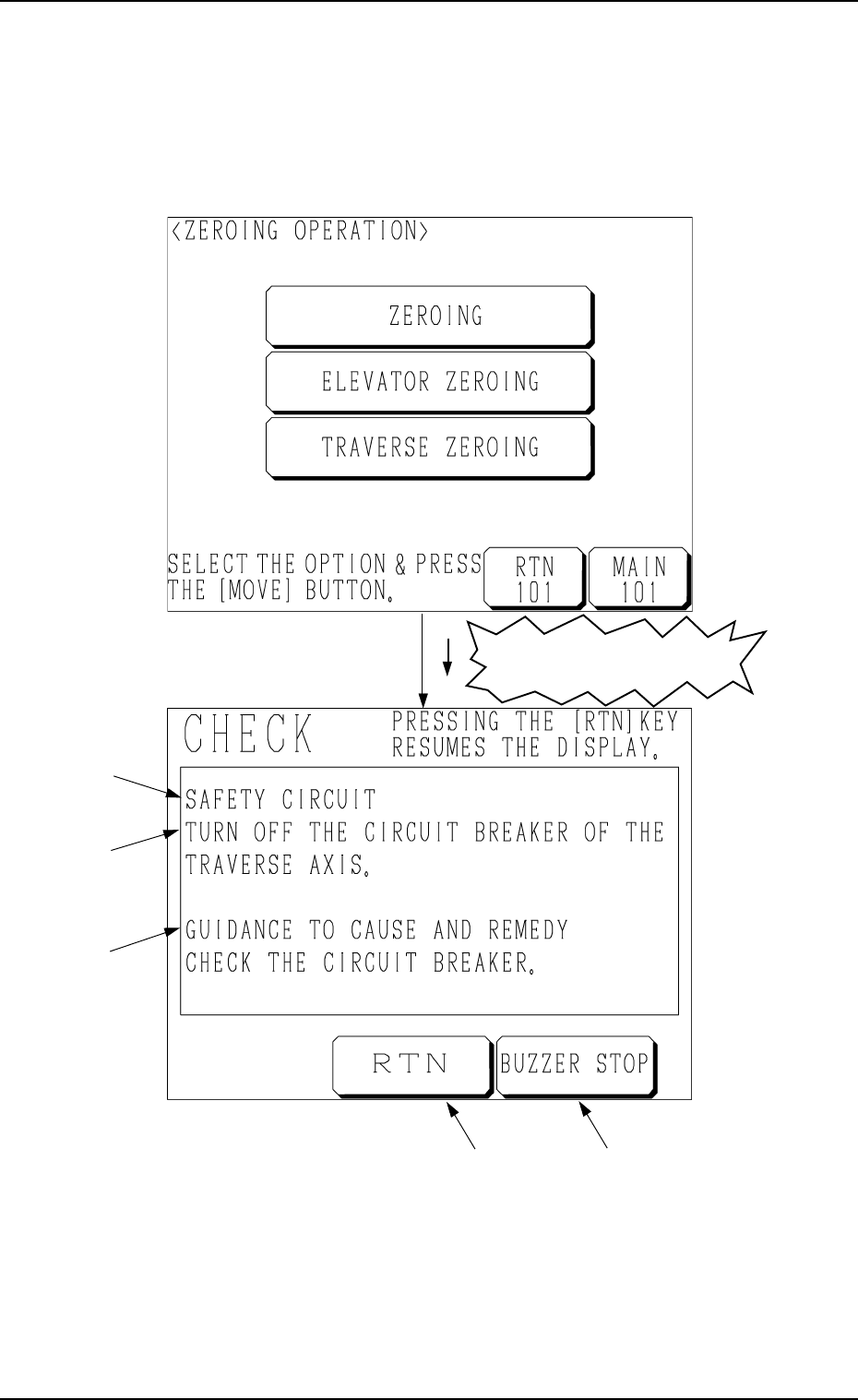
When a pushbutton on the operation panel is pressed under the condition that
requirements for a device to be activated are not fulfilled with the machine in
the “STOP” or the “PAUSE” mode, a “CHECK” display (Fig. 3.4) appears on
the screen.
1. Starting Guidance
A : Check Message
B : Description of Check Message
C : Guidance to Cause and Remedy of Nonfulfillment of Starting Require-
ments
D : This key is used to stop buzzer sound.
E : This key is used to stop buzzer sound and resume the display opened
before the “CHECK” display.
Refer to “3. List of Check Messages of Section 3 in Chapter 3” for details.
Fig. 3.4
A
B
C
ED
Fig. 3.3
Nonfulfillment of Starting
Requirements

9911-001 Chapter 3 3-3 Tg0252-PM-SO
2. Reset Procedure after Check Message
Operation Procedure
(1) Press the [BUZZER STOP] key. (See Fig. 3.4.)
The buzzer stops sounding.
(2) Check the contents of the check message and the remedial procedure
(GUIDANCE TO CAUSE AND REMEDY) displayed on the operation
monitor.
(3) Remove the cause of the nonfulfillment of starting requirements.
(4) Press the [RTN] key. The original display resumes.
2. Reset Procedure after Check Message

9911-001 Chapter 3 3-4 Tg0252-PM-SO
3. List of Check Messages
3. List of Check Messages
Item (Field *A) Description (Field *B)
Cause and Remedy (*C)
TURN OFF THE CIRCUIT
BREAKER OF THE TRAVERSE
AXIS
CHECK THE CIRCUIT BREAKER
POWER IS NOT SUPPLIED TO
THE TRAY UNIT
CLOSE THE COVER AND THE PRESS
THE [READY]BUTTON
SAFETY
CIRCUIT
THE TRAVERSE AXIS IS
APPROACHING ABNORMALLY
TURN OFF THE POWER AND KEEP
EACH TRAVERSE AXIS AWAY FROM
EACH OTHER
THE POSITION OF THE
TRAVERSE AXIS IS INDEFINITE
ZERO THE TRAY UNIT
TRAVERSE
AXIS
THIS MAY INTERFERE WITH
HEAD U/D AXIS ON MAIN BODY
SIDE.
ZERO HAED U/D AXIS (BEAM A)ON
MAIN BODY SIDE.
THE ELEVATOR AXIS IS NOT AT
ITS ORIGIN
ZERO THE ELEVATOR AXISELEVATOR
AXIS
FEEDER CARRIAGE IS EJECTED
FROM MAGAZINE.
CHECK THE CONDITION OF FEEDER
CARRIAGE.
THE MAGAZINE FOR FEEDER
CARRIAGE IS NOT CONNECTED.
CONNECT THE SELECTED
MAGAZINE AND PERFORM THE
ZEROING OPERATION.
FEEDER CARRIAGE DIRECTION
[BPH595] WAS DETECTED.
CHECK THE DIRECTION OF FEEDER
CARRIAGE IN UPPER AND LOWER
MAGAZINES.
UPPER DOOR
ELECTROMAGNETIC LOCK
SWITCH [SQ501] WAS NOT
DETECTED.
CHECK THE UPPER DOOR
ELECTROMAGNETIC LOCK SWITCH.
[READY (UPR)] LED [HD503]
WAS NOT DETECTED.
PRESS THE [READY (UPR)] BUTTON
TO SET UPPER MAGAZINE IN
READY MODE.
MAGAZINE
LOWER DOOR
ELECTROMAGNETIC LOCK
SWITCH [SQ502] WAS NOT
DETECTED.
CHECK THE LOWER DOOR
ELECTROMAGNETIC LOCK SWITCH.