OM-1068-001.pdf - 第125页
Background Color of Block Feeder Nos. (FDR. NO.) Shown are the feeder Nos. (FDR. NO.), the chuck matrix positions, the re- maining number of components, and the component IDs which belong to each individual blocks. Foreg…
11.1.3 Tray Chuck Matrix Change Operations
Refer to “7. Tray Pick-Up Matrix (Option) of Section 3 in Volume 1” in the
main machine instruction manual for details.
Operation Procedure
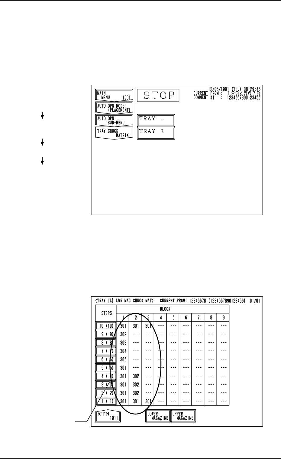
(1) When the [TRAY CHUCK MATRIX] key is pressed at the “AUTO OPN
SUB-MENU” display, the following display appears on the screen.
Fig. 1.48
Fig. 1.47
(2) Press the [TRAY L] or the [TRAY R] key to select the multi-layer tray
feeder L or R.
When the [TRAY L] or the [TRAY R] key is pressed, the following dis-
play appears on the screen.
(In this example, the “TRAY [L] LWR MAG CHUCK MAT” display is
shown. The display for “Tray R” looks like this.)
Hierarchical Sequence
(Display)
“MAIN MENU”
“AUTO OPN MODE
<PLACEMENT>”
“AUTO OPN SUB-MENU”
“TRAY CHUCK MATRIX”
11. Others
FDR. No.
0010-003 Chapter 1 2-41 Tg0252-PM-SO
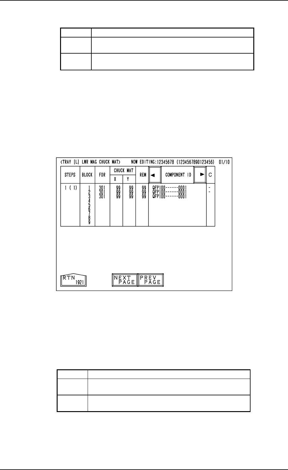
Background Color of Block Feeder Nos. (FDR. NO.)
Shown are the feeder Nos. (FDR. NO.), the chuck matrix positions, the re-
maining number of components, and the component IDs which belong to each
individual blocks.
Foreground Color of Feeder Nos. (FDR. NO.)
(3) When an arbitrary “STEPS” key is pressed, the “TRAY [L] LWR MAG
CHUCK MAT” display (the display for matrix indication/change) ap-
pears on the screen.
• Case: The machine is in the “RUN” mode (including the “WAIT” mode)
Shown are the matrix positions of the tray components to be picked up sub-
sequently. (Fig. 1.49)
The matrix cannot be changed while the machine is running.
11. Others
Fig. 1.49
Red This indicates that the block is short of components.
Green
This indicates that the block is used in the current
pattern program.
Black
This indicates that the block is not used in the current
pattern program.
Red This indicates that the block is short of components.
Green
This indicates that the block is used in the current
pattern program.
White
This indicates that the block is not used in the current
pattern program.
Table 1.8
Table 1.7
0010-002 Chapter 1 2-42 Tg0252-PM-SO
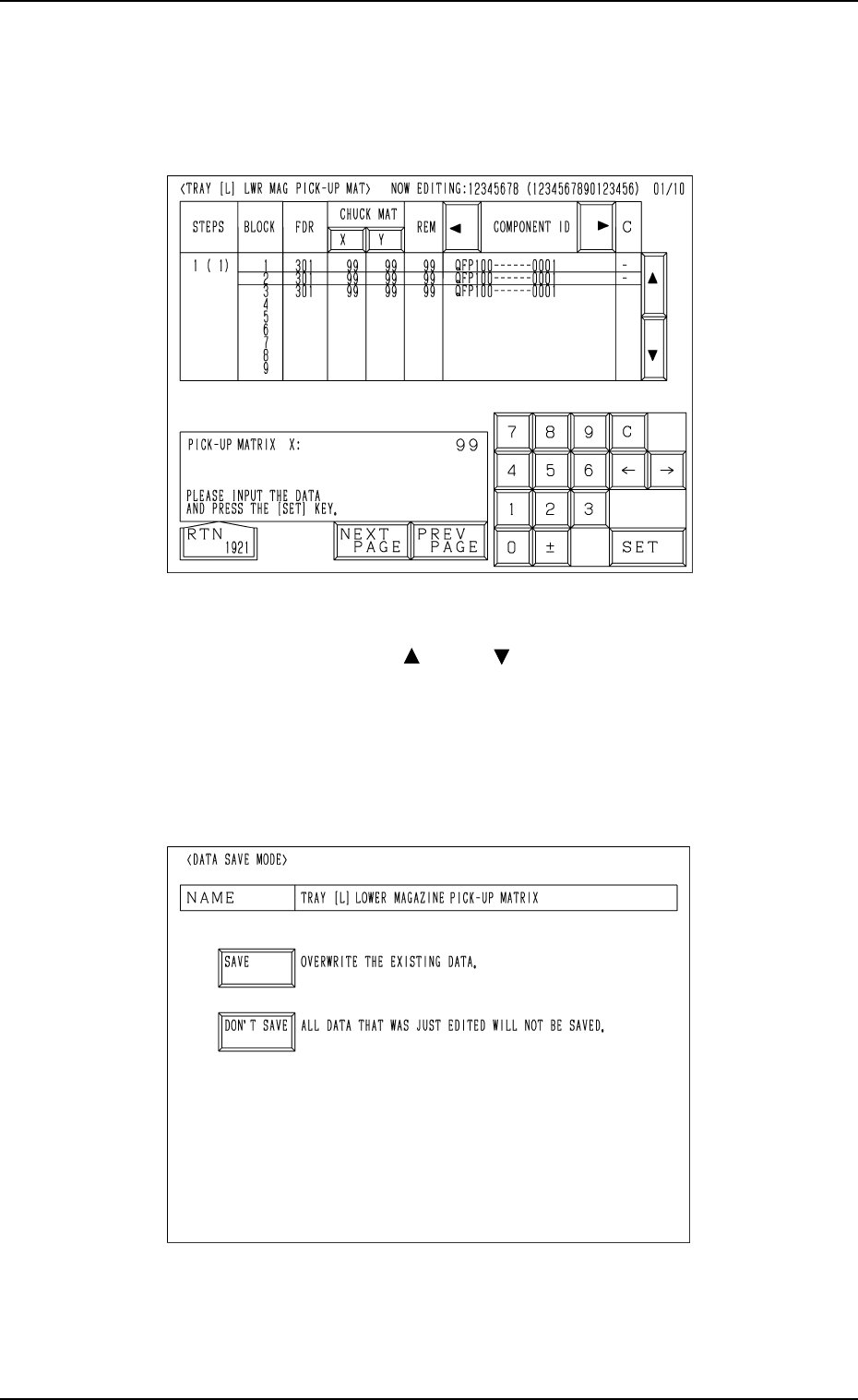
• Case: The machine is in the “STOP” or the “PAUSE” mode
Shown are the matrix positions of the tray components to be chucked subse-
quently. (Fig. 1.50)
The matrix can be changed while the machine is in the “STOP” or the
“PAUSE” mode.
Fig. 1.51
Fig. 1.50
To change the matrix, press the [ ] or the [ ] key to select the related block.
Select the [X] or the [Y] key, use the ten-key pad to specify the matrix posi-
tion, and press the [SET] key to define the parameters.
After the matrix position is defined, press the [RTN] key.
The “DATA SAVE MODE” display (Fig. 1.51) appears on the screen. To save
the changed matrix position, press the [SAVE] key. Otherwise, press the
[DON’T SAVE] key.
11. Others
0010-003 Chapter 1 2-43 Tg0252-PM-SO