OM-1068-001.pdf - 第259页
Chapter 5 2-2 Tg0252-PM-SO 1. Air Piping Diagram (FP-5021R) Upper Magazine (2) Clutch Connection Cylinder Lower Magazine (2) Clutch Connection Cylinder Upper Magazine (1) Clutch Connection Cylinder Lower Magazine (1) Clu…

9911-001 Chapter 5 2-1
Tg0252-PM-SO
Material (FP-5021R)
Section 2
Chapter 5 2-2 Tg0252-PM-SO
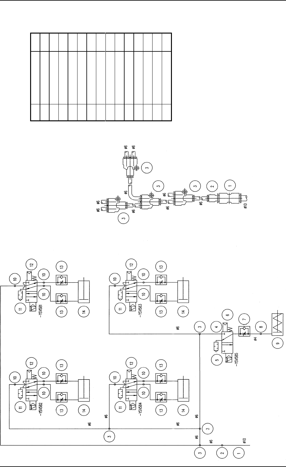
1. Air Piping Diagram (FP-5021R)
Upper Magazine (2)
Clutch Connection Cylinder
Lower Magazine
(2) Clutch
Connection
Cylinder
Upper Magazine (1)
Clutch Connection Cylinder
Lower Magazine (1)
Clutch Connection
Cylinder
To Upper Magazine (2)
Clutch Connection
To Lower Magazine (2)
Clutch Connection
To Lower Magazine (1)
Clutch Connection
Pallet Stopper
OFF
To Upper Magazine (1)
Clutch Connection
From TIM-5100 main machine
Details of Joint Connection
Pallet Stopper OFF Cylinder
From TIM-5100 main machine
1. Air Piping Diagram (FP-5021R)
No. Name Q t
y
1 Straight Union 1
2 Reducer 1
3 Union Y 4
4Half Union 1
5 Silencer 1
6 Solenoid Valve 1
7 Speed Controller 1
8 Elbow 1
9 Air Cylinder 1
10 Half Union 8
11 Silencer 4
12 Solenoid Valve 4
13 Speed Controller 8
14 Air Cylinder 4
9911-001-(M676XTL--1101)
Chapter 5 2-3 Tg0252-PM-SO
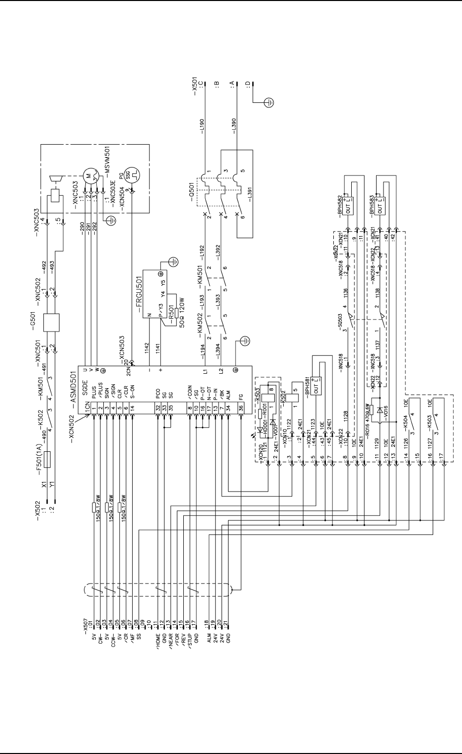
2. Electrical Circuit Diagrams
2.1 Elevator Circuit Diagram
2. Electrical Circuit Diagrams
Notes : (a) It shows the diagram within the dotted
lines is within the relay PCB.
(b) Use a pad of DS446 for the diode.
(c) For the diode DS446 is used.
Alarm
Brake
Elevator Shaft Origin
Elevator Shaft Overrun (+)
Elevator Shaft Limit (-)
Elevator Shaft
Encoder
Brake Power
Source
Brake
Emergency Stop
Alarm for Elevator Shaft
Note.b
0112-004 A(M742WTL--2101)