OM-1068-001.pdf - 第105页
5. Preparation and Confirmation before Operation Tg0252-PM-SO 5.2.3 Attachment and Detachment of Magazine 5.2.3.1 Attachment of Magazine Described below is how to attach the magazine to the internal sections of the eleva…
5. Preparation and Confirmation before Operation
Tg0252-PM-SO
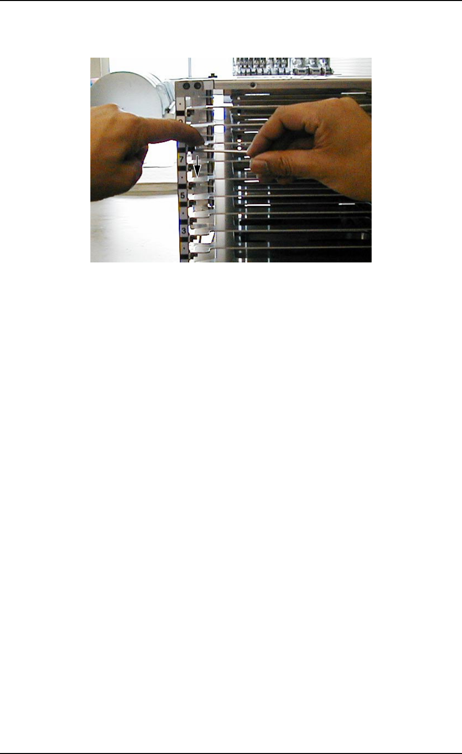
Fig. 1.27 Fix the partition plate. (Same for right and left.)
(5) Check visually that the partition plate is correctly placed on the block and
that the partition plate shows no warpage or deformation.
Note: If there is any nonconformity, repeat the attachment procedure
from the beginning because it might cause machine breakdown.
(4) Press the partition plate with the fingers so that it does not rise, as shown
in Fig. 1.27, and fix it with bolts (left and right, two locations)
9911-001 Chapter 1 2-21
5. Preparation and Confirmation before Operation
Tg0252-PM-SO
5.2.3 Attachment and Detachment of Magazine
5.2.3.1 Attachment of Magazine
Described below is how to attach the magazine to the internal sections of the
elevator for the first time after a multi-layer tray feeder is installed.
(1) Perform the zeroing operation.
Refer to “2. Zeroing Operation of Section 4 in Chapter 1” and “11.1.2
Zeroing Operation Maneuvered on Main Machine Side of Section 2 in
Chapter 1” for details.
(2) Press the [U READY] or the [L READY] button on the magazine loaded
side.
The LED of the pressed button extinguishes.
Ref.: While the LED of the [U READY] or the [L READY] button is
“ON”, the door (the upper or the lower door) cannot be opened.
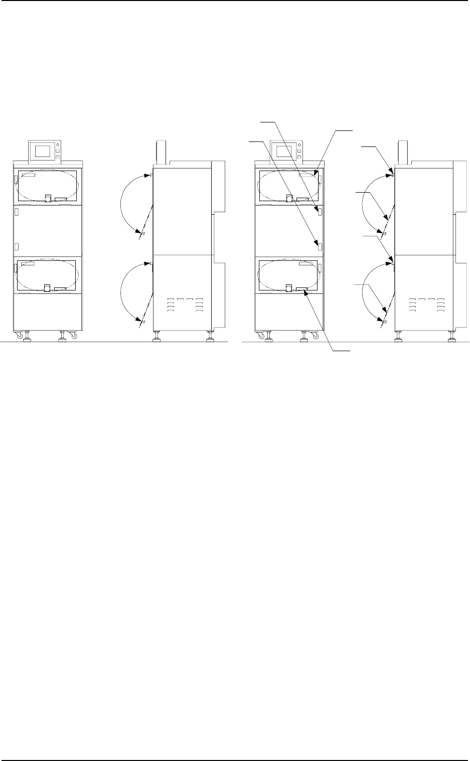
(3) Hold the grip of the door whose button is pressed in Step (2) and pull it
forward to open the door.
Fig. 1.28-1 Rough View (FP-5021L)
Fig. 1.28-2 Rough View (FP-5021R)
Magazine Base
Upper
Door
Lower
Door
Grip
Grip
[L READY] Button
[U READY] Button
Magazine Base
9911-001 Chapter 1 2-22
5. Preparation and Confirmation before Operation
Tg0252-PM-SO
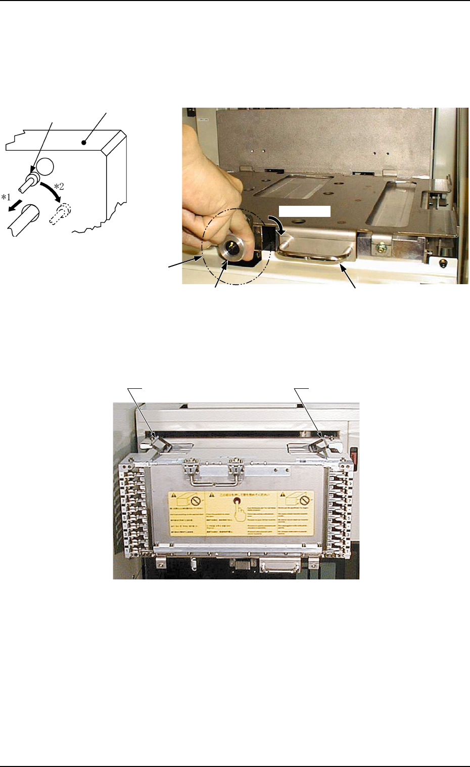
(4) Put the knob of the magazine stopper between fingers as
shown in Fig. 1.30 and turn it clockwise by approx. 90°
‹while pulling it forward.
(See Arrows *1 and *2 in Fig. 1.29.)
Ref.: Pulling Force of Magazine Stopper
39.2 N to 49.0 N (4 to 5 kgf)
Fig. 1.29
Fig. 1.31 Grips of Magazine “MG-5050L” (Same to “MG-5050R”)
(5) Hold the handle of the magazine base and pull it forward until it stops.
Locking Pin
Block
Fig. 1.30 Magazine Base
Knob Handle
Approx. 90°
Magazine Stopper
0112-003 Chapter 1 2-23
Grip of Magazine
Grip of Magazine