YV180X_Mainte_E.pdf - 第101页
4 -43 SED8013110 Service Manual Chapter 4 4 Machine adjust mode 8 Press the [ENTER] key when the camera is positioned. The Adjusting Method selection box then appears. 9 Select “ Use Standard V alue ” and press the [ENTE…
4
-42
Service Manual
Chapter 4
SED8013110
4
Machine adjust mode
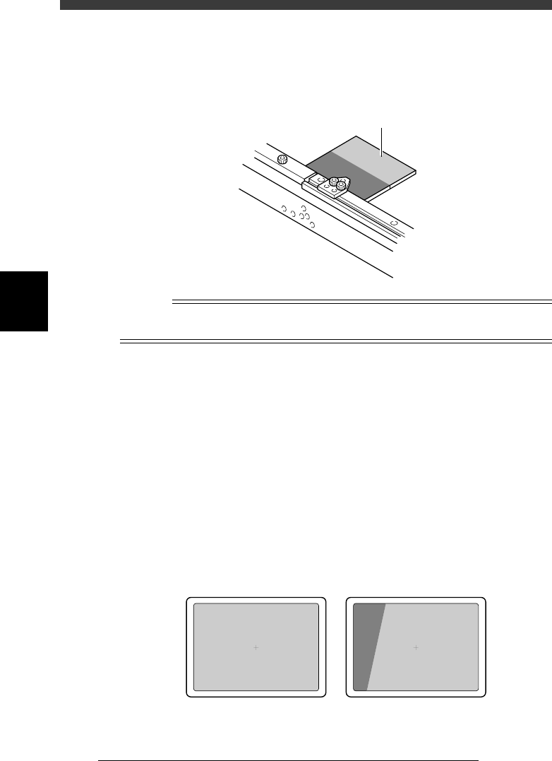
3 Set the light adjuster plate on the conveyor.
Set the light adjuster plate on the conveyor rail just above the fixed locate
pin, with the two-tone side facing up. Then run the PCB CLAMP command
in the CONVEYOR UNIT menu box so that the light adjuster plate is
clamped between the PCB support plate and the PCB side clamp.
43408-C0-00
Light adjuster plate
n
NOTE
As shown in the illustration below, set the dark gray edge of the light adjuster plate on the
conveyor rail just above the fixed locate pin, with the two-tone side facing up.
4 Cancel emergency stop after the light adjuster plate is
clamped on the conveyor.
Release the emergency stop button by turning it clockwise and press the
[READY] button.
5 Select “RETURN” from the CONVEYOR UNIT menu box
and press the [ENTER] key.
You can also use the [ESC] key to exit the CONVEYOR UNIT menu.
6 Check safety, then press the [ENTER] key.
The head assembly moves to above the locate pin and the teaching screen
for the light adjuster plate then appears.
7 Adjust the camera position.
While manipulating the YPU joystick, adjust the position of the moving
camera so that the light gray area on the light adjuster plate is displayed
over the entire field of view.
43416-C0-00
OK NG
4
-43
SED8013110
Service Manual
Chapter 4
4
Machine adjust mode
8 Press the [ENTER] key when the camera is positioned.
The Adjusting Method selection box then appears.
9 Select “Use Standard Value” and press the [ENTER] key.
47434-C0-00
Adjusting Method
Use Standard Value
Manual Input
Select lighting intensity value · · ·
A667
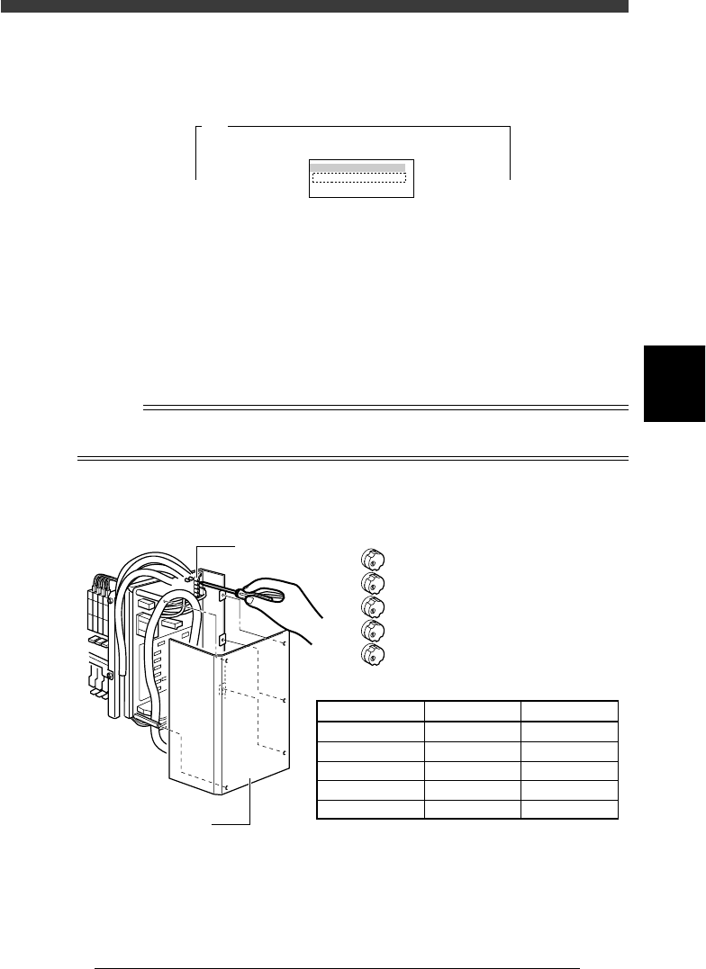
0 Press the emergency stop button, then adjust the moving
camera lighting level.
1. First adjust the LED trimmer VR1 on the I/O board.
By following the message displayed on the operation monitor, adjust
the LED trimmer VR1 so that the ”AveGrayLevel” value displayed at the
upper right of the screen matches the optimum level (30±1) shown in
the table below.
2. Adjust the LED trimmers VR2 to VR5 in the same way to set the
optimum levels.
n
NOTE
The LED trimmers VR1 to VR5 are arrayed from the top and their light levels increase by
turning the trimmer to the right (clockwise) and decrease by turning it to the left.
Moving camera lighting level adjustment
43409-D8-00
VR1
VR2
VR3
VR4
VR5
LED trimmer
I /O board cover
LED Trimmer
VR1
VR2
VR3
VR4
VR5
Lighting Zone
White-Outer
White-Inner
White-Coaxial
IR-Outer
IR-Inner
Optimum Level
30±1
30±1
12±1
30±1
30±1

4
-44
Service Manual
Chapter 4
SED8013110
4
Machine adjust mode
q Press the [ESC] key to quit the adjustment.
There is no machine data to be saved in this adjustment.
w Remove the light adjuster plate.
By following the message displayed on the operation monitor, unclamp
the PCB and then remove the PCB.