YV180X_Mainte_E.pdf - 第51页
3 -14 Service Manual Chapter 3 3 Machine data edit mode The illustration below sho ws an example when the front and rear feeder plates are respecti v ely di vided into 2 blocks (a total of 4 blocks), using feeder set num…

3
-13
Service Manual
Chapter 3
SED8013110
3
Machine data edit mode
4.1 Feeder plate offset
Current feeder plate settings and reference feeder positions can be checked
here. Teaching of the reference feeder positions can also be performed.
Feeder plate offset screen
47312-D8-00
<<<APPLICATION>>> 3/MAINTE/M
<<MODE>> 2/MCH_DATA
X
-183.016
489.650
617.580
745.660
891.490
0.000
0.000
OBJECT
FeederPlateOffset
TCH.UNIT SPEED
- - - - - - - -
Z
17.310
17.140
17.140
17.140
17.180
0.000
0.000
DatumNo.
2
10
18
26
30
0
0
Total
8
8
8
4
8
0
0
Plate No.
FeederPlate 1
FeederPlate 2
FeederPlate 3
FeederPlate 4
FeederPlate 5
FeederPlate 6
FeederPlate 7
Plate No. Feeder plates of this machine are divided into
blocks. In each of these blocks, a reference feeder
position is specified. The plate No. listed here
represents each block on the feeder plates. (Note
that Plate No. is different from feeder set numbers.)
Total Total number of feeder set positions that are allotted
to each block on the feeder plates. On standard
YV180X, the total figure should be 40 for each of
the front and rear feeder plates.
DatumNo. Feeder set number specified as a reference feeder
position. Any feeder set number within the block
can be specified as a reference feeder position.
X, Z Component pickup position and height (mm) when
a standard 8mm tape feeder is installed in the
reference feeder position.
3
-14
Service Manual
Chapter 3
3
Machine data edit mode
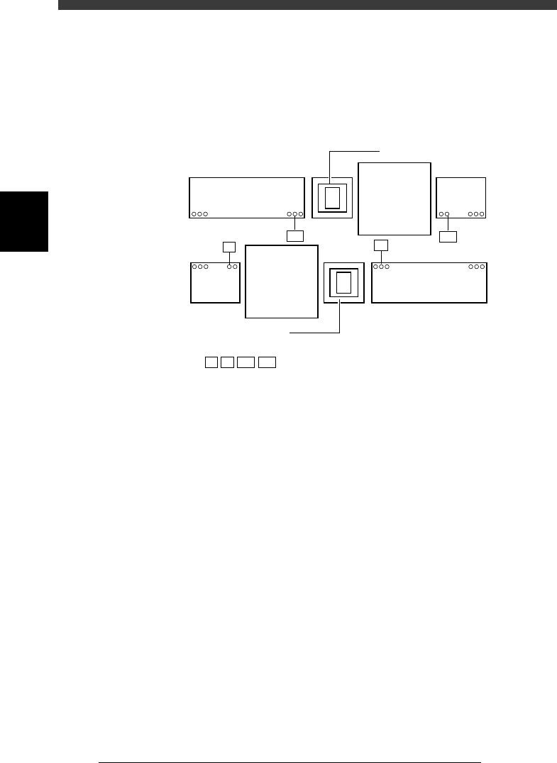
The illustration below shows an example when the front and rear feeder
plates are respectively divided into 2 blocks (a total of 4 blocks), using
feeder set numbers 7, 10, 107 and 110 as the reference feeder positions.
Correct coordinates of these reference feeder positions must be entered to
ensure accurate pickup of components.
Feeder plate reference positions (example)
43301-D8-00
140 109
101
19840
108
7
10
10
107
110
107
110
7
: Reference feeder positions
Multi-view camera
Multi-view camera
B table
A table
Feeder
plate
Feeder plate
Feeder plate
Feeder
plate
Correct coordinates of the reference feeder positions are set at the factory
prior to shipping. It is unlikely that you will have to re-teach these coordi-
nates. However, if for some reason re-teaching is needed, use the procedure
explained below using Head 1. (For reference feeder positions where Head
1 cannot reach, use Head 8.) Prepare 8mm tape feeders for small compo-
nents in advance.
e
1 Press the emergency stop button.
2 Check that a nozzle is attached to Head 1.
A nozzle for small chip components (for example, Type 72) is recom-
mended.
3 Set tape feeders at reference feeder positions.
4 Cancel emergency stop.
Check safety, then cancel the emergency stop button by turning it
clockwise and press the [READY] button.
3
-15
Service Manual
Chapter 3
SED8013110
3
Machine data edit mode
5 Open the shutter of the tape feeder.
1. Select <3/4/A1 FEEDER OUT MONITOR> and press the [ENTER] key.
2. Use the arrow keys to line up the cursor with the feeder numbers in
which you have set the tape feeders, then press the [ENTER] key.
The status display changes to “1” when the feeder is on (the shutter
opens).
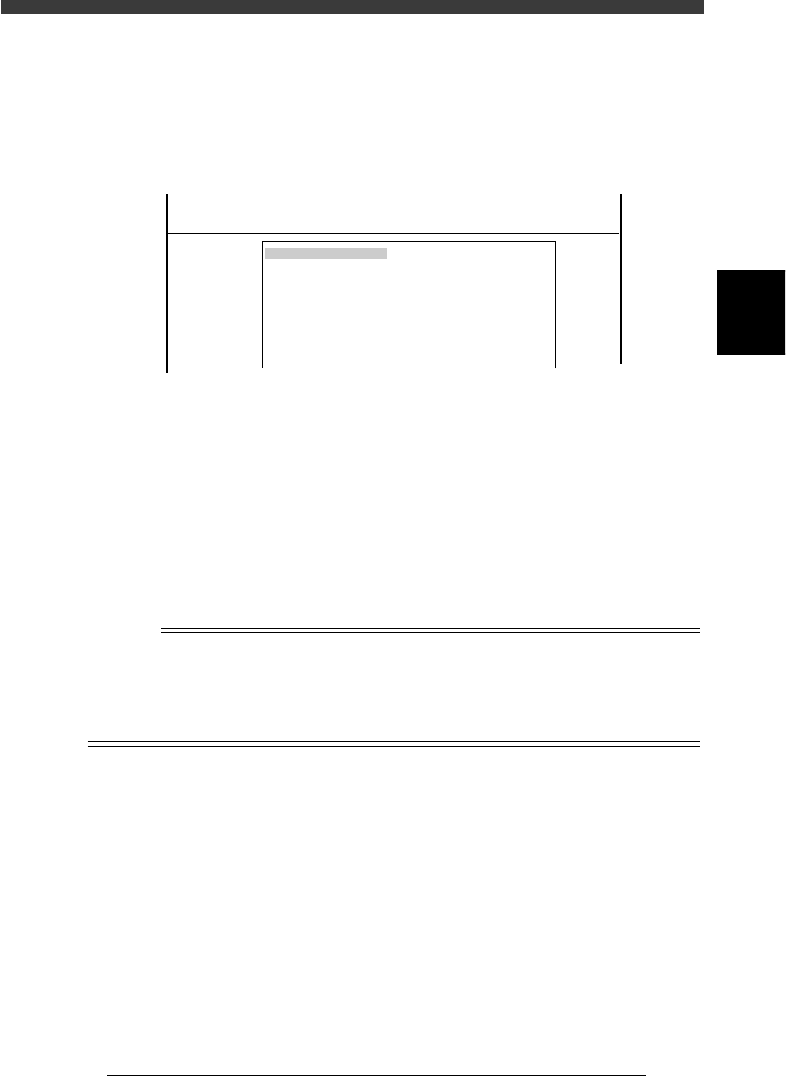
47313-D8-00
< FEEDER OPERATION >
1 - 8
9 - 16
17 - 24
25 - 32
33 - 40
41 - 48
49 - 56
57 - 64
00000000
00000000
00000000
00000000
00000000
/ / / / / / / /
/ / / / / / / /
/ / / / / / / /
101 - 108
109 - 116
117 - 124
125 - 132
133 - 140
141 - 148
149 - 156
157 - 164
<<<APPLICATION>>> 3/MAINTE/M
<<MODE>> 4/MANUAL
<COMMAND_LIST> A/IO_UTILITY
00000000
00000000
00000000
00000000
00000000
/ / / / / / / /
/ / / / / / / /
/ / / / / / / /
6 Move the head assembly to over the tape feeder.
1. Run <3/4/B1 SELECT SERVO MOTOR> or use the [SEL AXIS] or [AXIS
GROUP] key on the YPU to switch the selected axes to “A-table XY”
(or “B-table X”).
2. Manipulating the YPU joystick, move the head assembly to above the
component pickup position of the tape feeder.
3. Lower and position the head while switching the selected axes to “A-
table ZR” (or ”B-table ZR”) with the [SEL AXIS] or [AXIS GROUP] key,
so that the nozzle tip is at the center of the component.
Reference
To move the head assembly slowly for easier positioning work, use the <3/4/B2 RUNNING
SPEED> command to select a low speed. You can also perform fine-movements of the
head by slightly tilting the joystick in the desired direction.
As an alternative, under emergency stop conditions, rotating by hand the coupling that
links the X-axis motor shaft with the ball screw allows fine movement.