YV180X_Mainte_E.pdf - 第157页
7 -3 SED8013110 Service Manual Chapter 7 7 T roubleshooting 1. Pickup err ors 1.1 Chip components 45701-D8-00 Symptom Pickup error occurs in all feeders. Pickup error occurs in a specific head. Pickup error occurs for a …

Chapter 7
Troubleshooting
1. Pickup errors 7-3
1.1 Chip components .......................................................................................7-3
1.2 QFP components .......................................................................................7-4
2. Mounting errors 7-5
2.1 Chip components .......................................................................................7-5
2.2 QFP components .......................................................................................7-6
3. Recognition errors 7-7
3.1 Chip components .......................................................................................7-7
3.2 QFP components .......................................................................................7-8
3.3 Mark ..........................................................................................................7-9
4. Conveyor 7-10
5. Feeder 7-11
6. FNC nozzles 7-12
7. Others 7-13
Chapter 7 describes possible causes and corrective action for typical
errors which may occur during daily operation.
7
-3
SED8013110
Service Manual
Chapter 7
7
Troubleshooting
1. Pickup errors
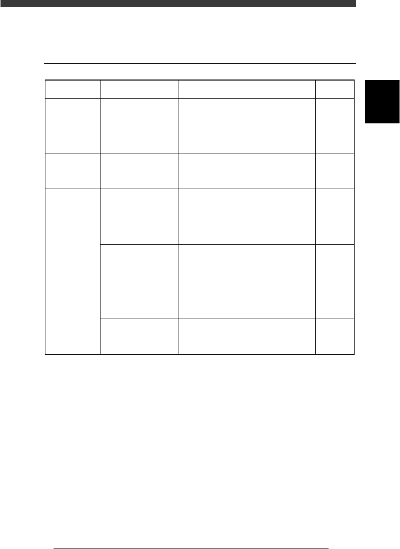
1.1 Chip components
45701-D8-00
Symptom
Pickup error
occurs in all
feeders.
Pickup error
occurs in a
specific head.
Pickup error
occurs for a
specific
component.
Possible cause
The nozzle does not
reach components, or
the pickup point is not
correct.
The head offset X, Y
or Z data is incorrect.
The feeder is not
properly installed, or
the tape feeder has a
problem.
The nozzle tip does
not reach the
components, or the
pickup positions are
incorrect.
The reference pickup
vacuum level is
incorrect.
Corrective action
If the nozzle does not reach the
component, then readjust the "Z" value
on the Feeder PlateOffset screen. When
the pickup position shifts, perform
teaching for the feeder plate.
Test-mount components and adjust the
"Head offset X, Y" values based on the
results obtained.
Detach the feeder from the feeder plate
and check for tape feed. If tape feed is
not smooth, replace the feeder. Also
check that no loose chip components
remain at the feeder set position.
If the nozzle does not reach the
component, increase the "Pick Height"
value of the PICK & MOUNT
parameters in the component i
nformation. When the pickup position
shifts, perform reteaching for the pickup
position in the component information.
Increase the reference pickup vacuum
level.
Refer to
4.1 in
Chapter 3
AMF
manual
Feeder
user's
manual
Mounter
operation
manual
2.1 in
Chapter 3
7
-4
Service Manual
Chapter 7
SED8013110
7
Troubleshooting
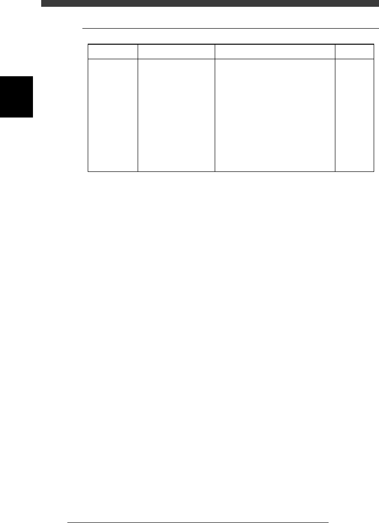
1.2 QFP components
45702-D8-00
The head is
picking up
components,
but "pickup
error" is
indicated.
Symptom Possible cause
Air leakage due to the
uneven surface of the
QFP, or "Vacuum
Check" of the PICK &
MOUNT INFO.
parameters in the
component information
is set to "SPECIAL
CHK" and the vacuum
pressure does not meet
the "Pick Vacuum"
setting level.
Corrective action
Reduce the "Pick Vacuum" pressure
setting in the component information.
Refer to
Mounter
operation
manual