YV180X_Mainte_E.pdf - 第141页
6 -3 SED8013110 Service Manual Chapter 6 6 Conveyor unit and air supply unit adjustment 1. Adjusting the conveyor unit Each mechanism of the conveyor unit is arranged along the conveyor rails and operates by air pressure…

Chapter 6
Conveyor unit and air supply
unit adjustment
This chapter explains how to adjust the conveyor units used to
transfer and clamp PCBs, and also how to set the optimum air
pressure for pneumatic-driven units.
1. Adjusting the conveyor unit 6-3
1.1 Adjusting the air valve................................................................................6-4
1.2 Conveyor speed .........................................................................................6-6
1.3 Adjusting the conveyor belt tension ...........................................................6-9
1.4 Adjusting the W-axis initial position .........................................................6-10
1.5 Y-axis (A/B table) initial position............................................................... 6-11
1.6 PCB detection sensors ..............................................................................6-13
2. Air supply unit 6-16
2.1 Air pressure regulator ...............................................................................6-16
2.2 Pressure-drop detection level ...................................................................6-17
6
-3
SED8013110
Service Manual
Chapter 6
6
Conveyor unit and air supply unit adjustment
1. Adjusting the conveyor unit
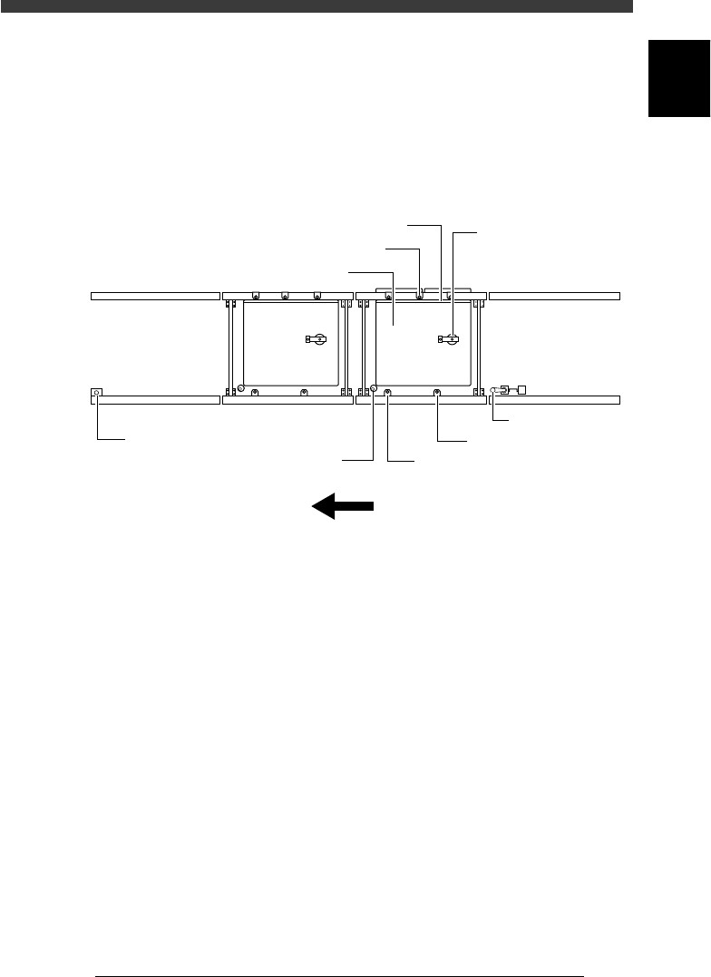
Each mechanism of the conveyor unit is arranged along the conveyor rails
and operates by air pressure or a servo motor. These conveyor units are
preadjusted at the factory prior to shipping. If for some reasons adjustment
becomes necessary, refer to the description in this section.
Conveyor units (right-to-left flow)
43601-D8-00
Pushup plate
Edge clamp (option)
Pushup pin
Entrance stopper
Movable locate pin
Fixed locate pin
Direction of PCB flow
B table conveyorA table conveyor
Exit stopper
Main stopper
PCB clamp
Carry-out conveyor
Carry-in conveyor
6
-4
Service Manual
Chapter 6
SED8013110
6
Conveyor unit and air supply unit adjustment
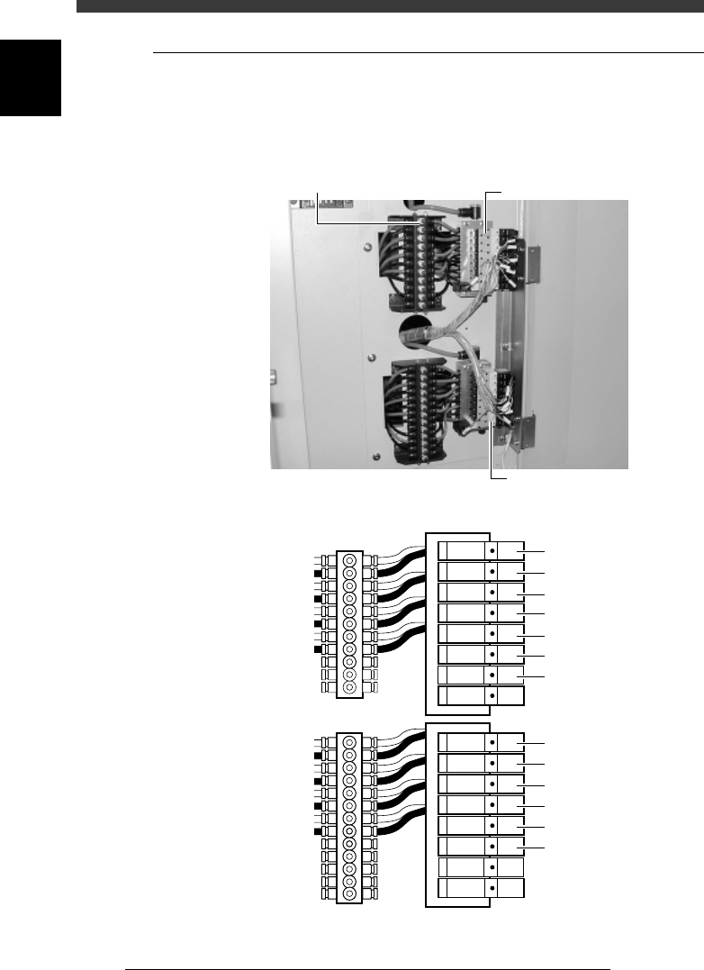
1.1 Adjusting the air valve
The air valve of each conveyor unit mechanism is located inside the lower
right panel on the back of the machine. Air drive speed can be adjusted by
turning the speed controller knob connected to each air valve.
Air valves for conveyor unit operation
43610-D8-00
Speed controller
Air valve
Air valve
Air valve
T1920 : Miain stopper
Orange : Ascent speed
Black : Descent speed
T1921 : Pushup
T1922 : Locate pin
T1923 : Edge clamp
T1930 : PCB clamp
T1926 : Exit stopper
T1925 : Entrance stopper
<
A table
>
T1932 : Miain stopper
T1933 : Pushup
T1934 : Locate pin
T1935 : Edge clamp
T1931 : PCB clamp
T1937 : Transfer hook
<
B Table
>
Speed controller