YV180X_Mainte_E.pdf - 第94页
4 -36 Service Manual Chapter 4 SED8013110 4 Machine adjust mode 3 Select the nozzle type to perform the test. When the Measuring Nozzle Selection box appears, select the nozzle to perform the vacuum level test and press …
4
-35
SED8013110
Service Manual
Chapter 4
4
Machine adjust mode
3.3.2 Mount vacuum level
When a nozzle descends to mount a component on the PCB, the vacuum
pressure at the nozzle is instantaneously inverted to a positive pressure, so
the vacuum sensor detects a lower value. When this detected level becomes
lower than the preset mount vacuum level, the machine determines that the
component has separated from the nozzle and is now mounted on the PCB.
The mount vacuum level should be preset for each head, at a level slightly
lower (offset value: 5) than the maximum vacuum level maintained when
the nozzle opening is sealed.
When measuring the vacuum level by selecting “All Nozzle Common” (see
step 1), attach Type 72 nozzles to all heads in advance.
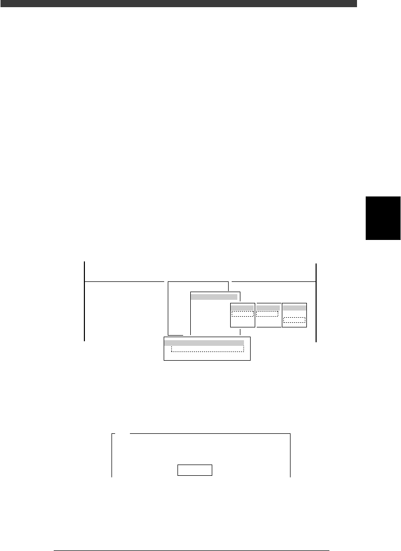
1 Run the Vacuum Level command.
1. Select <3/3/B1 ADJUST TARGET> − ”Vacuum Level” and press the
[ENTER] key.
2. Select “Each Nozzle” or “All Nozzle Common” and press the [ENTER]
key.
3. Select A table” (or “B table”) − “ALL” − ”Mount” and press the [ENTER]
key.
47423-D8-A0
B1 ADJUST TARGET
Object
Vacuum Level
<<<APPLICATION>>> 3/MAINTE/M
<<MODE>> 3/MCH_ADJUST
<COMMAND_LIST> B/SAVE & QUIT
tabale
Atable
Btable
Head
ALL
Key in
Target
Pick
Mount
Vaccum Level Measuring Way
Each Nozzle
All Nozzle Common
2 Confirm that [offset 5] is displayed, and press the [ENTER]
key.
An offset of “5” is recommended.
47424-C0-00
A441
Please enter the vaccum level offset value.
The picking vaccum level equals the vaccum level when
the nozzle is......
Offset 5
4
-36
Service Manual
Chapter 4
SED8013110
4
Machine adjust mode
3 Select the nozzle type to perform the test.
When the Measuring Nozzle Selection box appears, select the nozzle to
perform the vacuum level test and press the [ENTER] key. (The Measuring
Nozzle Selection box does not appear when “All Nozzle Common” was
selected in step 1.)
e
4 Press the emergency stop button, then seal the nozzle holes
tightly.
Seal the nozzle holes of all heads tightly with items such as carrier tape so
that air does not leak out.
5 When preparation is complete, cancel emergency stop.
Check safety, then release the emergency stop button and press the
[READY] button.
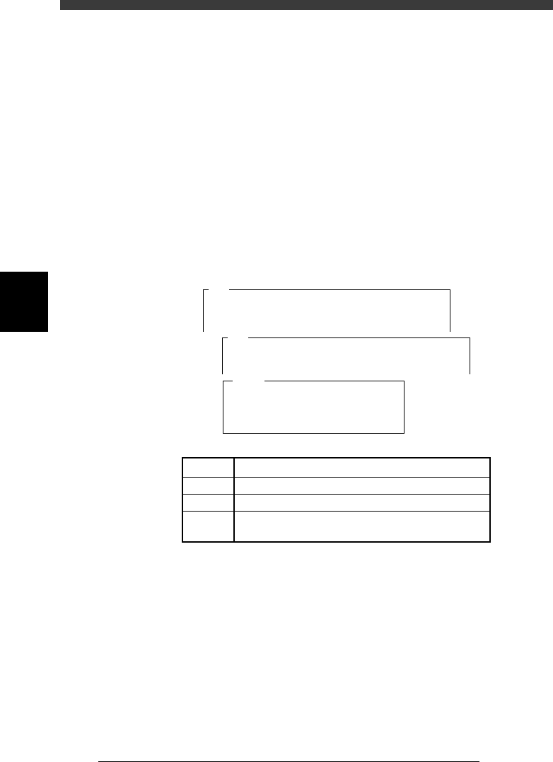
6 Press the [ENTER] key to start test.
The mount vacuum level is measured for about 8 to 20 seconds and the
results are then displayed.
47427-D8-00
Level
Max.
Current
Result
1
XX
XX
XX
XX
2
XX
XX
XX
XX
3
XX
XX
XX
XX
4
XX
XX
XX
XX
5
XX
XX
XX
XX
6
XX
XX
XX
XX
7
XX
XX
XX
XX
8
XX
XX
XX
XX
Atable
A492
<<<Measuring>>>
The vaccum level of TYPE - 71 nozzle is
now being measured.
Measurement.....
A494
The vaccum level during mounting of
TYPE - 71 nozzle will be measured.
For this adjustment a component must be attached....
5C04330-00
LEVEL
Min.
Current
Result
Real-time vacuum level being measured.
Minimum vacuum level during measurement
Mount vacuum level specified as machine data
Measurement results (Equal to the minimum vacuum
level with an offset of 5 subtracted)
7 Quit the test according to instructions on the operation
monitor.
Press the [ENTER] key to save the results, or press the [ESC] key to cancel
them.
8 Save the results.
Select <B2 SAVE DATA> or <B0 SAVE & QUIT> and press the [ENTER]
key. (To quit without saving, select <B3 RECOVER ADJUST> or <B7
QUIT> and press the [ENTER] key.)
e
9 Press the emergency stop button.
Check safety, then remove the items you used to seal the nozzles holes.
4
-37
SED8013110
Service Manual
Chapter 4
4
Machine adjust mode
3.4 Moving camera
The moving camera is installed in the head assembly and used to recognize
PCB fiducial marks or perform coordinate teaching. The focus, lighting
level and the scale of the moving camera must be adjusted correctly.
Adjustment items for moving camera
45404-D8-00
FOV & Focus
Brightness
Camera Scale
A PCB having clear characters or marks to be focused is used.
For more accurate adjustment, use of a glass PCB is recommended.
A light adjuster plate (KV1-M8806-0XX) is used.
A PCB having marks of accurate dimensions is used
For more accurate adjustment, use of a glass PCB is recommended.
Adjustment items Description
Moving camera and lighting unit
43415-D8-00
Moving camera
Recognizes the marks
on a PCB or performs
teaching or tracing.
I/O board cover
LED for moving
camera
Used to illuminate
marks on the PCB.
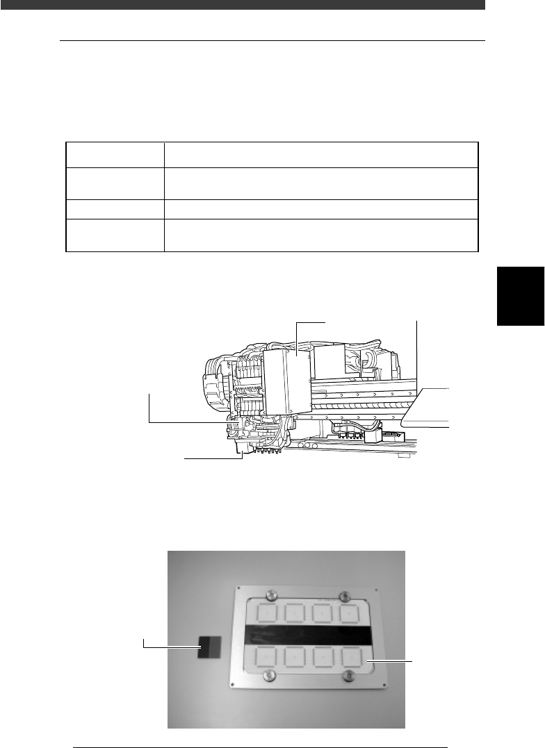
Adjustment tools (option) for moving camera
43420-D8-00
Light adjuster
(KV1-M8806-0XX)
Glass PC
B