YV180X_Mainte_E.pdf - 第177页
s-1 SED8013110 Index Index Symbols [Ctrl] + [ENTER] keys 1-8 [F1] key 2-3, 2-6 [F10] key 4-71 [F9] key 4-71 A Adjust Assistant For mark recognition 4-46 For reference marker 4-66 Adjust target menu 4-10 Adjustment tools …
8
-10
Service Manual
Chapter 8
SED8013110
8
Power and machine connections
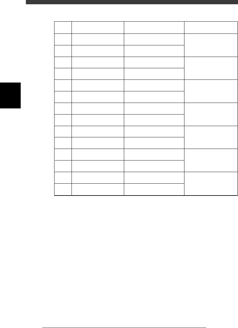
PCB transfer signal specifications
45803-C0-00
1
2
3
4
5
6
7
8
9
10
11
12
13
14
BUSY IN (+24V)
BUSY IN (N1113)
BA OUT (T1832)
BA OUT (T1832)
NC
NC
NC
NC
UR OUT (T1833)
UR OUT (T1833)
LR IN (+24V)
LR IN (N1116)
COUNT RESET (+24V)
COUNT RESET (+24V)
Pin No.
Signal name
I/O specifications Signal specifications
+24V
Tr input
Relay contact (zero voltage)
output
Relay contact (zero voltage)
output
Relay contact (zero voltage)
output
Relay contact (zero voltage)
output
+24V
Tr input
+24V
Tr input
Signal input during PCB
carry-in
Signal output to request
PCB carry-out
Signal output during
automatic operation
Signal input during
automatic operation
Signal input for COUNT
RESET

s-1SED8013110
Index
Index
Symbols
[Ctrl] + [ENTER] keys 1-8
[F1] key 2-3, 2-6
[F10] key 4-71
[F9] key 4-71
A
Adjust Assistant
For mark recognition 4-46
For reference marker 4-66
Adjust target menu 4-10
Adjustment tools
For moving camera 4-37
For multi-vision camera 4-50
Air pressure regulator 6-16
Air supply unit 6-16
Air valve for conveyor unit 6-4
AveGrayLevel 4-43
Axis configuration 4-13
B
Breaker 8-5
Brightness level
Moving camera 4-41
Multi-vision camera 4-55
C
Camera, Machine data edit mode 3-10
Camera scale
Moving camera 4-45
Multi-vision camera 4-58
Caution 3
Change nozzle 4-7, 5-7
Change speed 4-8
Conv. Correct, Position parameter 4-32
Conveyor belt tension 6-9
Conveyor speed 6-6
Conveyor unit adjustment 6-3
Conveyor units command 5-7
Coordinate/spec, Machine data edit mode
3-10
D
Daily inspection 1-4
Discard point, Position parameter 4-21
Down offset, Machine data edit mode 3-7
Dual-direction recognition offset 4-62
Dump box 4-21
Dump component command 4-7
Dump station 4-28
Dump stn.point, Position parameter 4-27
E
Edge clamp, Position parameters 4-18
Error
Conveyor 7-10
Feeder 7-11
FNC nozzle 7-12
Mounting error 7-5
Others 7-13
Pickup error 7-3
Recognition error 7-7
Exit from manual 5-10
F
Feeder out monitor 5-6
Feeder plate information 1-14
Feeder plate offset; Machine data edit mode
3-13
Feeder spec information 1-17
File configuration 1-11
FINE mode; Position parameter 4-15
Flying nozzle information 1-13
FOV & focus
Moving camera 4-38
Multi-vision camera 4-51
G
Grease 1-10
H
Head down valve 4-8
Head spec information 1-13
Head; Machine data edit mode 3-4

s-2
SED8013110
Index
I
I/O utility menu 5-4
Initial movement 4-12
Initial position 4-12
R-axis 4-12
T-axis 4-12
W-axis 6-10
Y-axis 6-11
Initialize servo origin 5-9
Input/output monitor 5-5
INPUT/OUTPUT MONITOR command 5-4
Inspection
6-month inspection 1-9
Daily inspection 1-4
Monthly inspection 1-9
Weekly inspection 1-8
Inspection and maintenance 1-4
L
Light adjuster plate 4-41, 4-55
Lighting level
Moving camera 4-41
Multi-vision camera 4-55
Locate pin position, Position parameter 4-
15
M
Machine Adjust mode 4-3
Machine Configuration mode 2-5
Machine Data Edit mode 3-3
Machine maintenance utility 1-12
Maintenance manager 2-3
Manual mode 5-3
Marker
Multi-vision camera 4-65
Mount vacuum level 4-35
Mounting error 7-5
Chip component 7-5
QFP component 7-6
Moving camera 4-37
Camera scale 4-45
FOV & focus 4-38
Lighting level 4-41
Multi-vision camera 4-50
Brightness level 4-55
Camera scale 4-58
Dual-direction recognition offset 4-62
FOV & focus 4-51
Marker 4-65
MultiCam Marker; Machine data edit mode
3-21
N
NEXT INTERFACE circuit 8-9
Nozzle clog prevention air blow 4-20
Nozzle correction; Machine data edit mode
3-8
Nozzle spec information 1-15
O
OPTION CONFIG. mode
Basic menu 2-6
Detail menu 1-8
Option configuration 2-6
P
PCB detection sensors 6-13
PCB Height, Position parameter 4-22
Pickup component command 4-5
Pickup error 7-3
Chip component 7-3
QFP component 7-4
Pickup vacuum level 4-33
Pickup/mount vacuum levels 4-33
Point move command 5-9
Position (machine coordinates) 3-19, 4-14
Power connections 8-4
Power requirements 8-3
Precautions 1-3
Precision; Machine data edit mode 3-21
Pressure-drop detection level 6-17
PREVIOUS INTERFACE circuit 8-7
Q
QFP clearance, Position parameter 4-26
R
R axis accuracy; Machine data edit mode
3-9
R-axis accuracy offset 4-67
R-axis initial position 4-12
Recognition error 7-7
Chip component 7-7
Mark 7-9
QFP component 7-8
Retry Limit, Position parameter 4-26