YV180X_Mainte_E.pdf - 第125页
4 -67 SED8013110 Service Manual Chapter 4 4 Machine adjust mode 3.6 R-axis accuracy of fset This is the angular of fset for the R-axis that rotates each nozzle shaft to mount a component. When you select <3/2/A1 SELEC…
4
-66
Service Manual
Chapter 4
SED8013110
4
Machine adjust mode
5 Save the data.
Select <B2 SAVE DATA> or <B0 SAVE & QUIT> and press the [ENTER]
key. (To quit without saving, select <B3 RECOVER ADJUST> or <B7
QUIT> and press the [ENTER] key.)
Reference
The marker offset values adjusted here are stored in “Precision” - “MultiCam Marker” in
MCH_DATA mode. (See “6.1” in Chapter 3.)
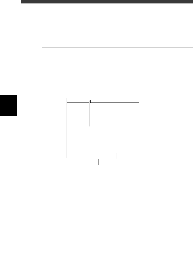
6 Check the data.
Enter the Adjust Assistant mode in DATA Manager and run the VISION
TEST command for the marker using any component data (not necessary to
actually pick up acomponent with the nozzle) and check that the [Marker
2] XY data values displayed on the lower part the Adjust Assistant screen
are within ±0.005.
Adjust Assistant screen after VISION TEST
47460-D8-00
Comp. Name : QFP208pin-0.5P
Command
PICK UP COMP.
*
VISION TEST
PARAM. SEARCH
DISCARD COMP.
DRAW THE SHAPE
CHK GRAY VALUE
EXIT
Adjust Assist Items
Feeder Set No.
Comp. Tolerance
Comp. Threshold
Lighting Level
Search Area
Monitoe Mode
Condition Chk.ModeROW
40
30
30
0.80
3 / 8
Nothing
ROW
(%)
(mm)
VO
(X= 0.000, Y= 0.000, R= 0.000)
Component was detected successfully.
Position and angle data is available.
[ Marker 2 ] (X= 0.002, Y= -0.002)
Check that these values are within
±
0.005.

4
-67
SED8013110
Service Manual
Chapter 4
4
Machine adjust mode
3.6 R-axis accuracy offset
This is the angular offset for the R-axis that rotates each nozzle shaft to
mount a component. When you select <3/2/A1 SELECT TARGET > - ”R
Axis Accuracy” and press the [ENTER] key, the current offset settings for
mounting angles of 0, 180, 90 and -90 degrees are displayed as shown
below.
R Axis Accuracy offset screen
47407-C0-00
<<<APPLICATION>>> 3/MAINTE/M
<<MODE>> 2/MCH_DATA
Head No.
Head 1 A
Head 2 A
Head 3 A
Head 4 A
Head 5 A
Head 6 A
Head 7 A
Head 8 A
0°
0.000
0.000
0.000
0.000
0.000
0.000
0.000
0.000
OBJECT
Coordinate/Spec
TCH.UNIT SPEED
- - - - - - - -
180°
-0.166
0.000
0.091
0.342
0.000
0.091
0.246
0.000
90°
0.000
0.020
1.140
0.000
0.000
0.005
0.060
0.390
-90°
-0.305
0.000
-0.386
0.000
0.005
-0.099
0.000
0.002
When the multi-vision camera with the reference mounting angle specified
at 0 degrees is used, mountings at 90, 180 and -90 degrees might deviate
slightly. This deviation or offset can be corrected with the R Axis Accuracy
command in the MCH_ADJUST mode, in which the multi-vision camera
recognizes an SOP component at each mounting angle to obtain the offset
with respect to the recognition result at 0 degrees. Since the parameter at 0
degrees is used as a reference, it is always set to 0.00 degrees.
4
-68
Service Manual
Chapter 4
SED8013110
4
Machine adjust mode
To determine these offset settings, use the R Axis Accuracy command in
the Maintenance Manager. The machine automatically evaluates these
offset settings by recognizing the component that a head picks up while
rotating the nozzle shaft at the four angles of 0, 180, 90 and -90 degrees.
n
NOTE
If the reference mounting angle itself has deviated, the camera angle (R coordinate in the
CameraCoordinate parameters) must be corrected.
1 Prepare a component to be used as a reference.
Use a relatively large, popular component of known size which is
registered in the component database.
Reference
SOP components such as “No.704; SOP16-P1.27-6.4W” are recommended. If you are
going to use tape feeder components, install the tape feeder on the feeder plate in
advance.
e
2 Press the emergency stop button, then attach the nozzle
that matches the component.
You can skip this step for FNC heads.
3 Cancel emergency stop.
Check safety, then release the emergency stop button and press the
[READY] button.
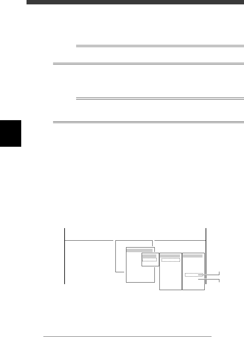
4 Run the R Axis Accuracy command.
1. Select <3/3/B1 ADJUST TARGET> - "R Axis Accuracy" and press the
[ENTER] key.
2. Select the conveyor table, head No. and camera No. by pressing the
[ENTER] key.
The A-table multi-vision camera is designated “Cam. 5” and the B-table
multi-vision camera “Cam. 6”.
47454-D8-00
B1 ADJUST TARGET
Object
R Axis Accuracy
<<<APPLICATION>>> 3/MAINTE/M
<<MODE>> 3/MCH_ADJUST
<COMMAND_LIST> B/SAVE & QUIT
Target
A table
B table
Target
Cam. 1
Cam. 2
Cam. 3
Cam. 4
Cam. 5
Cam. 6
Cam. 7
Cam. 8
Head No
Head 1
Head 2
Head 3
Head 4
Head 5
Head 6
Head 7
Head 8
A Table
Multi Camer
a
B Table
Multi Camer
a