YV180X_Mainte_E.pdf - 第46页
3 -9 Service Manual 3 Machine data edit mode Chapter 3 SED8013110 2.5 R axis accuracy Selecting “ R Axis Accuracy ” from the “ Head ” submenu opens the R Axis Accuracy screen as sho wn below . Data entered here are offse…
3
-8
Service Manual
Chapter 3
3
Machine data edit mode
SED8013110
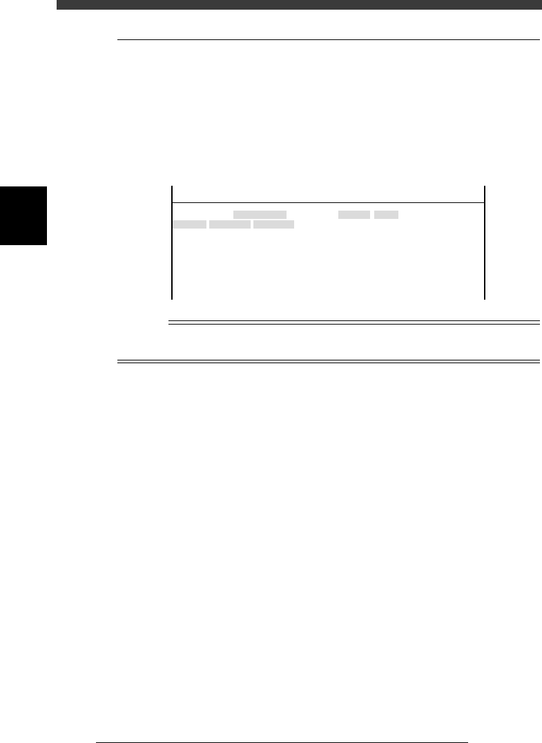
2.4 Nozzle correction
Selecting “NozzleCorrection” from the “Head” submenu opens the Nozzle
Correction screen as shown below. Data entered here are offset settings
(mm) for correcting a positional shift of the center of each head. These
positional shifts for example occur if the nozzle shaft is bent an amount
equal to the difference between recognition height and mounting height
even though nozzle angle remains the same.
Nozzle Correction screen
47306-D8-00
<<<APPLICATION>>> 3/MAINTE/M
<<MODE>> 2/MCH_DATA
Head No.
Head 1 A
Head 2 A
Head 3 A
Head 4 A
Head 5 A
Head 6 A
Head 7 A
Head 8 A
OBJECT
NozzleCorrection
TCH.UNIT SPEED
- - - - - - - -
Y
0.000
0.000
0.000
0.000
0.000
0.000
0.000
0.000
X
0.000
0.000
0.000
0.000
0.000
0.000
0.000
0.000
n
NOTE
Nozzle correction can be automatically adjusted by running the AMF (auto mount
feedback) utility. See the separate AMF manual for details.
3
-9
Service Manual
3
Machine data edit mode
Chapter 3
SED8013110
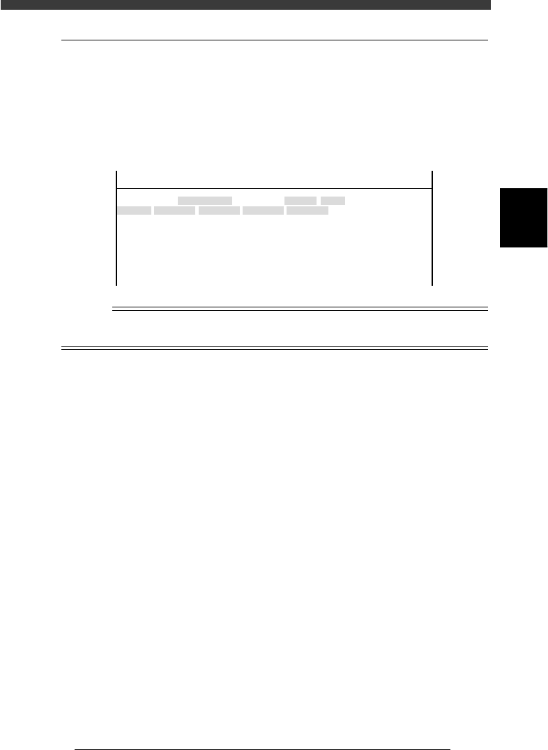
2.5 R axis accuracy
Selecting “R Axis Accuracy” from the “Head” submenu opens the R Axis
Accuracy screen as shown below. Data entered here are offset settings
(deg.) for correcting the mounting angles of each head at 0, 180, 90 and -90
deg. Since this parameter at is used as a reference at 0 degrees, it is always
set to “0.000”.
R Axis Accuracy screen
47307-C0-00
<<<APPLICATION>>> 3/MAINTE/M
<<MODE>> 2/MCH_DATA
Head No.
Head 1 A
Head 2 A
Head 3 A
Head 4 A
Head 5 A
Head 6 A
Head 7 A
Head 8 A
OBJECT
R Axis Accuracy
TCH.UNIT SPEED
- - - - - - - -
0°
0.000
0.000
0.000
0.000
0.000
0.000
0.000
0.000
180°
0.000
0.000
0.000
0.000
0.000
0.000
0.000
0.000
90°
0.000
0.000
0.000
0.000
0.000
0.000
0.000
0.000
-90°
0.000
0.000
0.000
0.000
0.000
0.000
0.000
0.000
n
NOTE
R axis accuracy can be automatically adjusted by running the R Axis Accuracy command
in MCH_ADUST mode.
3
-10
Service Manual
Chapter 3
3
Machine data edit mode
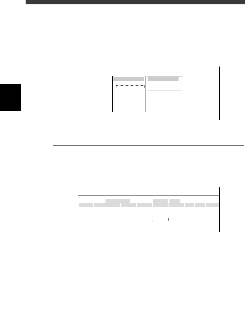
3. Camera
When “Camera” is selected from the <3/2/MCH_DATA> main menu, the
submenu appears as shown below. Each item on this submenu is explained
in the following sections.
Submenu box when “Camera” is selected
47308-C0-00
SUB MENU
Coordinate/Spec
Vision Parameter
MCHDATA SORT
Head
Camera
Machine
Tray Changer
Station
Other
Precision
Spare Data
<<<APPLICATION>>> 3/MAINTE/M
<<MODE>> 2/MCH_DATA
3.1 Coordinate/spec
Selecting “Coordinate/Spec” from the “Camera” submenu opens the
Coordinate/Spec screen as shown below. Data entered here are coordinates
and lighting type of each camera used in this machine.
Coordinate/Spec screen
47309-D8-00
<<<APPLICATION>>> 3/MAINTE/M
<<MODE>> 2/MCH_DATA
Cam No.
Cam 1A
Cam 3A
Cam 5A
Cam 2A
Cam 4B
Cam 6B
X
152.042
0.000
382.925
-152.051
0.000
472.334
OBJECT
Coorcinate/Spec
TCH.UNIT SPEED
- - - - - - - -
Y
-0.166
0.000
0.091
0.446
0.000
-0.064
Z
0.000
0.000
17.140
0.000
0.000
17.390
R
-0.305
0.000
-0.386
-0.099
0.000
-0.515
Type
Move
- - - - - - - - - - - - -
Dig.Multi
Move
- - - - - - - - - - - - -
Dig.Multi
Size
0
0
45
0
0
45
Max Z
0
0
7
0
0
7
Light Sp
TypeA
TypeA
TypeG
TypeA
TypeA
TypeG
X, Y Moving camera: XY position (mm) of camera center
from the head reference position
Multi camera: XY position (mm) of camera center
from the machine origin.
Z Height (mm) of bottom of component while being
recognized with the multi camera.
R Camera installation angle (deg.)
Size Maximum component size recognizable in XY
directions
Height Maximum component height (mm) recognizable in
Z direction
Light Sp Lighting type for each camera